What's new
What's new

New to me Van Norman 26

There is some bad information about VFD drives above.
If you have a machine tool with multiple motors and want
to run off one VFD, you absolutely can.
A strategy that works well, it to wire the VFD directly to the
main motor. Branch off this feed to the main motor, and feed
the switches or contactors that run the smaller motors.
Things like power feed motors or coolant pump motors.
In this way, with the main motor constantly connected to the
VFD, there is no circuit being broken. The VFD is happy.
As for the switching of the other motors, the VFD is protected
from inductinve spikes from the switch contacts by the riunning
main motor. Spikes on the line are just pee in the pool on the
line feeding the running motor.
The worry about many motors confusing the VFD is not an issue
if you use a Volts-Hertz configured VFD. If you bought the more
expensive sensorless vector VFD, you can run it in Volts-Herts
mode, as you really don't need that feature. I have sensorless
vector mode turned off on my milling machine VFD, because it
has so much torque, that it will snap a tap when rigid tapping
holding a tap in the drill chuck.
That is as simple as I can explain it. Buy a VFD to support the
total horsepower of all the motors, and buy the basic Volts-Hertz
model. If you wire the VFD output straight to the main motor, and
branch off for your switched accessory motors, you will never hurt
the VFD.

FWIW- I own a VN22LU


--Doozer
Thank you for that information.

I decided to go for two VFDs because it gives me the ability to independently speed control eachmotors at almost the same price.

The Invertek drives that I bought from Wolf Automation were 2HP $266 and 3HP $366 ($632 total). A 5HP drive to control both motors would have been $628. So, for the same price I gained the ability to fine tune each motor to it’s drive and got two speed control.
 
Last edited:
Interesting dominant use of solid wire. The terminals
on the VFD may not be rated to accept solid wire,
even though it might fit. The solid wire can pressure
the terminal strips that are directly soldered to the
curcuit board, and any stress can break a copper trace
on the board. Check the manual for recommendations
on this.
Pro tip... Hook the wire around the terminal screws
so the clockwise tightening will tighten the hook of
the bend, not try and open it. Also I see some of
the terminal screws spitting the hook out from under
the screw. Another bad condition with diminished
clamping and low conductivity.
Also, it looks like you have uninsulated ground wire
inside BX armored cable. Not typical code.
And the use of air hose as a sheath for the control
wires is "creative". The magnets on the control box
will soon reveal themselves as not the best idea.

-Doozer
-Yeah I have spool of 10AWG solid wire so I decided to use that. I will crimp Y forks on the VFD connection side to prevent any issues there. Good tip
- The motor cabe are actually proper VFD cables. The armor is grounded on both ends but I'm not using the appropriate grouding connectors, they were not available or too expensive. It has three uninsulated ground cable running simetrycally around the conductors.
1679064391554.png
 
And thanks for the good write up and pictures.
I believe my VN22LU might look a bit the same
inside, if I ever need to take it apart some day.
You are right, all the online manuals are bad.

-Doozer
 
Got a lot of work done one the machine this weekend and it’s all back together and running now.

The Y axis power feed lever felt loose and would not properly disengage the gear when put in neutral. I had to overshoot it and then come back to neutral to disengage it. While I had the front knee cover off I decided to take a look at that system.

2023-03-21_09-35-30.jpg2023-03-21_09-37-57.jpg
I found that there was a lot of play in the transmission fork. Segment 26-891 and Fork 26-890 were loose on the shaft so I figured I would need to tighten them. I was contemplating the amount of stuff that I would have to remove to get to the set screws when I noticed that there are two access holes that give you direct access to the set screws! The more I work on this machine the more I like it.
2023-03-21_09-41-14.jpg
I tightened both of them and now it is a lot better but it stil doesn’t shift right. I looks like the fork shoes are worn out quite a bit so there is still a lot of slack in the assembly. I guess people pulled on this lever hard for years to compensate for the slack in the forks and it ended up wearing out the shoes. At some point I will replace them but not now, it’s a project for future me.
 
Last edited:
Ok here is my 2 cents on how to put the feed speed lever assembly back into the knee somewhat easily.

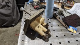
Here are some pictures of the assembly.
PXL_20230317_201951132.jpg

PXL_20230317_201958994.jpg

PXL_20230317_202213648.jpg

PXL_20230317_202906693.jpg

You can see that it consists of two plates, one of them move vertically and has a vertical rack, the other one moves horizontally and has a matching rack. These plates are held in specific positions by spring loaded detents machined in the main body. These two rack mesh with two pinions that in turn create movement on the two transmission forks in the knee. There is also a third pinion at the back of the assembly that activates the high and low range. This selector is also retained in three different positions by a spring detent, but that mechanism is not accessible at that level of disassembly.

Putting this back together is tricky because 1) As you are trying to put this back in the knee, transmission fork can move on you and change the gear alignment and 2) The cover plate that holds all of this mechanism together, also hides the SHCS that mount the assembly to the knee…

So here is what I did with a buddy.

-In the knee, move transmission fork 1 to its leftmost position and fork 2 to its rightmost position. Take some time to fine tune the gear alignment. This speed is the only one in which the second pinon will not have to slide on top of fork 1 to reach fork 2. That is going to help preserve the gear alignment you just did as you are putting the assembly back in

-The high-low range selector naturally rests in the high position. This is fine but you have to make sure the clutch is fully engaged in the high position. You have to have the other cover off or use a borescope verify that.

-Assemble the whole feed selector assembly together including the front plate (using only two of the flat head screws.) Shift to the top right speed and engage the range selector to the high position (just like on the picture).

Ok everything is ready to be put back together now.

-Engage the Z power feed lever as if you were trying to get the knee to go up

-Engage the knee binder

-Have your buddy use the Knee hand crank as if he was trying to get the knee to go down. We are not trying to create any movement of the knee, just bind the gears together to create some tension.

At this point the speed selecting gears can’t easily slide back and forth on their shaft because of the tension. That is going to help the forks stay were you positioned them as you are putting the assembly back in.

Next step is to carefully put the whole assembly back in the knee. Try to tilt everything so the pinions are high and at the very end they engage in a top down motion in their racks.

Now we need to remove the cover so we can put the 4 assembly bolts in, but we need to keep everything in its place so we don’t lose our internal alignment. Remember that the selecting plates are spring loaded with the detents, so they are going pop out of position when you remove the cover. You need to keep applying some pressure on the selecting plates as your buddy is working around you to:

-Remove the two flat head screws and the cover

-Install the 4 SHCS

-Re-install the cover and the screws.

Here you go, it's done. It was long write-up but it’s actually pretty easy to perform these steps and we were able to put the gearbox in and out multiple times with a perfect gear alignment each time. I hope it encourages some people to open up their machine and take a look inside.
 
Last edited:
jdbouchard60, if I could give ten "likes" for that, I would. This summer I need to dig into that part of my VN28A knee, and that photo walk-though will be super helpful.
 
Hey I' m glad you are enjoying the content. I hope this will be helpful to someone in the future.

Next on the list is the ram gearbox. There are some weird noises coming out of the ram when I’m engaging the middle speed column from the top lever and run the spindle.

I opened the cover and at first glace most of the gears look pristine. The oil had a metallic sheen to it, kinda like car spray paint with metal glitter in it. I assume this is metal dust from wear on the gears be it is extremely fine and there were 0 chunks of metal so I think over all I’m in good shape.

There are 2 issues that I can spot though.

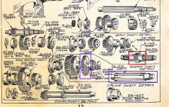
First issue is that the gear that transmits power from the second speed change shaft to the High/low shaft has some big time play in it. Highlighted blue on the diagram
2023-03-28_14-37-20.jpg
You can check this video of the problem.

https://photos.app.goo.gl/1jjm7uvy7zctDtmY6

It seems like loose woodruff key is the theme with this machine so far… Unfortunately, I can’t see any set screw to fix the problem this time.

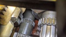
The second issue is that every single shaft seems to have excessive side to side motion. This result in some poor gear meshing and seems to have caused a lot of wear and tear on a tiny gear on the intermediate shaft (red on the diagram). This gear is the one engaged when I hear the bad noises with the spindle is running. I think that it probably has some nasty burrs and that some file work would improve the noise issue and protects the other gears.
PXL_20230328_131448330.jpg
So, I think there is a ram gearbox teardown in my future to gain access to these two gears that need some attention. At this point I will remove all the shafts except the pinion shaft to check all the bearings and add shims where needed to ensure proper gear mesh. Whish me luck.

Also, I foud this on Ebay for a decent price. Pretty excited about that.
s-l1600 (2).jpg
 
Last edited:
PXL_20230329_122132363.jpg
Hey guys just a quick wrap up of my gearbox teardown. It was not a bad job at all, so I didn’t feel like doing a full write up on it but here are a few pointers:

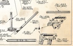
-After removing the top plate, the first step is to remove the two rods that hold the transmissions forks in place (blue arrows). They are held in place by set screws accessible from the top of the casting (yellow arrows). Sorry I don’t have a picture for that. The rods can simply be carefully punched out of the top casting. There is a spring-loaded ball in each transmission fork, and it is held captive by the rod. As you are pushing the rod out, try to push a snug rod or a socket to replace it and keep the ball captive. Otherwise, it is just going to fly out and they are a pain to put back together.
2023-04-19_16-27-45.jpg
-Once the rods are out you can remove the transmission fork. From there the disassembly process is straight forward. Remove the bearing covers, slide the splined shafts out leaving all the gears inside the casting. You can then remove the gears from the top opening. The High/low gear on the shaft 26-411 is held captive by a split washer. Removing cap 26-424 and spacer 26-429 will allow you to create some relative motion between the gear and the shaft. You need to push the shaft toward the spindle as you are pulling the gears towards you. Doing so will reveal the split washer and then the whole shaft can be pulled out.

2023-04-19_16-31-57.jpg
- The bearing covers that are flush to the casting can be tricky to remove. A strong magnet was useful to pull them out.

-The parts labeled as “knockout washer” on the diagram are just spacers between the bearing blind holes. There is a M12x1.75 thread in the middle of these knockout washers so you can fasten them to a slide to remove the blind hole bearings.
2023-04-19_16-24-37.jpg
-There are 7 (10-405) bearings, they are equivalent to SKF 6306 and are relatively inexpensive, so I replaced them all. The other bigger bearings were still in good shape and looked more expensive, so I didn’t mess with them. I also replace both shaft oil seal 7898 and 7896 with National 471750 and 471785.


Back
Top