What's new
What's new

Pratt & Whitney C clutch removal

Peroni

Cast Iron
Joined
May 18, 2007
Location
Yadkinville, NC
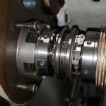
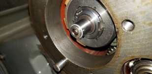
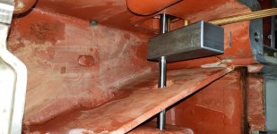
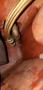
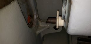
New to me 1957 12 x 30 model C lathe I just picked up from a fellow forum member. I need to remove the main clutch for servicing and repair. I've got the drive pulley and housing off and the "clutch shaft bearing housing dowel" removed but I cannot get the main clutch assy to move. The section view in the manual is a bit crowded and hard for me to see. It looks like the oil pump is driven via a slot in end of the clutch shaft. I can't tell if the pump is bolted to the clutch brake housing or headstock casting? Hopefully someone has been down this road before?

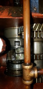
clutch rear.jpg clutch top.jpg

And the counterweight on the clutch control rod shaft - can it be loosened by removing and reaching in thru the oil filter housing or does the headstock need to come off? Bell crank end of that shaft if buggered up and contributing to the clutch problems. It may be able to be fixed in situ but I'd rather replace it with a new one.
 
New to me 1957 12 x 30 model C lathe I just picked up from a fellow forum member. I need to remove the main clutch for servicing and repair. I've got the drive pulley and housing off and the "clutch shaft bearing housing dowel" removed but I cannot get the main clutch assy to move. The section view in the manual is a bit crowded and hard for me to see. It looks like the oil pump is driven via a slot in end of the clutch shaft. I can't tell if the pump is bolted to the clutch brake housing or headstock casting? Hopefully someone has been down this road before?

View attachment 366027 View attachment 366028

And the counterweight on the clutch control rod shaft - can it be loosened by removing and reaching in thru the oil filter housing or does the headstock need to come off? Bell crank end of that shaft if buggered up and contributing to the clutch problems. It may be able to be fixed in situ but I'd rather replace it with a new one.
Find #28 screwed (?) into back of HS and remove same and see if that frees up anything. Its the "Clutch Shaft Bearing Housing Dowel". .
 
New to me 1957 12 x 30 model C lathe I just picked up from a fellow forum member. I need to remove the main clutch for servicing and repair. I've got the drive pulley and housing off and the "clutch shaft bearing housing dowel" removed but I cannot get the main clutch assy to move. The section view in the manual is a bit crowded and hard for me to see. It looks like the oil pump is driven via a slot in end of the clutch shaft. I can't tell if the pump is bolted to the clutch brake housing or headstock casting? Hopefully someone has been down this road before?

View attachment 366027 View attachment 366028

And the counterweight on the clutch control rod shaft - can it be loosened by removing and reaching in thru the oil filter housing or does the headstock need to come off? Bell crank end of that shaft if buggered up and contributing to the clutch problems. It may be able to be fixed in situ but I'd rather replace it with a new one.
I didn’t have to pull the clutch on my Pratt & Whitney 12C, but I think that this clutch might come out as a complete assembly. I’ve worked on other lathes that were like this. I think if you pull the shifting fork, the oil pump piping, and a threaded pin on the back of the headstock and then remove the shaft next to this one (I believe P&W calls it the first shaft), it will come out as a unit. But this is just a hunch.

Are you sure the clutch is bad? The shifting levers on the back of the headstock are secured by tapers on the shafts and are infinitely adjustable. It is easy for it to be slightly off and lose either the clutch or the braking. You’ve probably already checked this, but just a thought.

As far as the counterweight, you can access it by removing the oil pump housing and the front housing cover where it makes the transition. I believe the counterweight is keyed and has a set screw.
 
I didn’t have to pull the clutch on my Pratt & Whitney 12C, but I think that this clutch might come out as a complete assembly. I’ve worked on other lathes that were like this. I think if you pull the shifting fork, the oil pump piping, and a threaded pin on the back of the headstock and then remove the shaft next to this one (I believe P&W calls it the first shaft), it will come out as a unit. But this is just a hunch.
It's out! But oh man what a royal pain in the ass it was! You were right shaft #52 had to come out along with the gears. But then shaft #37 has to be pulled out as far as it can go so gear #31 can be tied up out of the way. It cannot be removed due to a boss on the backside of gear and shaft 31 will only go forward so far until gear #35 hits gear #70. You can't remove that gear cluster without taking the spindle out. It's like mechanical Tetris in there! With screw #28 out you can then tap on pump from the flow sight opening. But it's not so simple as removing the whole unit as the pump does not fit though the bearing bore - by just a tiny bit no less! Removing the 3 screws that hold the pump on was not a pleasant task. But once that is done the clutch, shaft w/ bearing and brake housing can be slid back, tip the pump drive end up and it comes out the top of headstock. Likewise the pump can be turned on end and squeezed past the gears and out the top.

Now to find out why the clutch assembly slides back and forth on the clutch shaft by about 3/32......
 
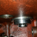
Chucked up the pump and turned it .010 smaller than the flange so now the whole thing can pass through the bearing bore. Now the pump can be installed on end of the clutch shaft BEFORE it gets stuffed down in the headstock. I don' know why this detail was overlooked on such a well engineered lathe.

Found out someone in the past was in the clutch and put the set screw that locks the clutch body to the shaft in reverse order. A dog point screw goes in first and locks into a hole in the shaft then a plain set screw goes on top of that to lock it in place. These were reversed and not even tight so the whole thing slid back and forth and galled up the parts pretty good. Some people have no business repairing equipment.... :wrong:
Pump.jpg
 
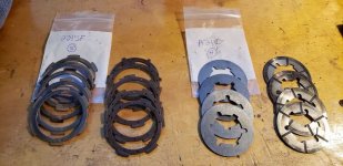
I got new clutch plates from Palmer Johnson, they're an in stock item and part numbers are written on the bags for reference. Beware the new frictions are an updated design that measure 3/32 thick vs 1/16 for the originals. You install one less set of the new plates than what was originally in there.
20220615_174733.jpg

Here is the mostly assembled clutch. Notice the welded up repair on the gear housing. P&W was reluctant to scrap any parts it seems.
20220616_181554.jpg

Modified pump bolted in place. I still need to fix the drive end bearing. A long out of production and unmarked needle bearing was used between the clutch shaft and drive housing. 3 small oil holes provided a trickle of oil to this bearing but were plugged with sludge. As this bearing wore it allowed the plates to rattle and wear ridges in both the clutch and drive bodies. It also wore the little 5/8 tail shaft so it is no longer suitable for a bearing surface. I'm going to press on a hardened drill bushing to bring that shaft up to 3/4. I have a new caged needle bearing that will fit in the drive body and accept the new 3/4 tail shaft.
20220616_182000.jpg
 
Here are a few more photos in case someone down the road needs to do some work on their P&W clutch. Install did not go quite as planned due to not being able to fit clutch assy and pump into headstock with the other gear shafts in place. If the headstock was empty it would have worked however the solution wasn't too bad.

With pump removed the clutch can be carefully placed in headstock and then slid into the input shaft hole. Turns out this is a nice fit with the clutch's brake housing. All of this is poking out the back of headstock.
1655752343754.png

There is plenty of room to get the pump on and the whole assembly can be rotated to get at all 3 bolts with ease. Note that this will only work if you turn the pump body down!
1655752358211.png

With the pump in place the whole unit can be slid forward and seated in its bore keeping in mind to clock it so the retaining dowel can be screwed in place from outside the headstock.
1655752375613.png

And for the record there is no way to remove either the oil filter housing or clutch lever shaft w/ counterweight unless you pull the headstock. The oil supply pipes and check valve prevent the filter housing from being removed and these can only be accessed from inside of the sump. To gain access the headstock has to be removed. And you're not removing the shaft and counterweight without getting that housing off. Fortunately the headstock comes off rather easy and it's probably a good thing I took mine off as the sump is FILTHY.
1655752763674.png
 

Attachments

  • 1655752758232.png
    1655752758232.png
    196.2 KB · Views: 4
Thanks for documenting this. I'm glad the clutch on my 16" isn't asking for attention at the moment! But when it does this should be useful.
 
A hardened drill bushing proved to be a perfect fix for the worn tail end of the clutch shaft.
20220625_154433.jpg

With the sump cleaned and a new shaft made the clutch lever counterweight is reinstalled. While it could point up or down the factory parts book shows it pointing up.
20220625_133309.jpg

Details of the oil lines going to/from the oil filter that feeds the distribution piping in headstock.
20220625_133349.jpg
 
Last edited:
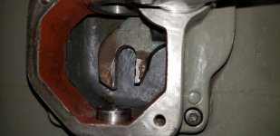
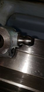
This piece is on the operator's end of the same shaft the counterweight is attached to. The fork had some wear so I welded it up with Palco 808 rod and machined for a close fit with the mating ball.
20220625_152155.jpg

The ball also had some wear. It was rotated 90° and re-drilled for the taper pin. This mechanism transmits the up and down motion of the apron clutch lever to the rocking motion that will actually move the clutch shifter fork. End of the apron clutch lever shaft goes into the QCGB and when this lever is operated, it also actuated an oil pump. So not only do the clutch levers have to be in correct time and orientation to the clutch itself but also that little pump.
20220625_152215.jpg
 
Last edited:
I was wondering how chips had gotten into the sump as it is rather well sealed, well here is the culprit and the fix. You're looking at the oil return pipe for the feed ratio gearbox. Oil is fed via a tube in top of the headstock and it trickles down thru this gearbox and out the bottom tube that pokes thru a cast hole in the sump. The hole is rather large and while somewhat protected, is a path foreign objects can make their way into the sump. I cut a simple felt cover backed up with some felt washers. This sealed around the return tube and covered the opening to the sump nicely so nothing can get in there.
20220625_193349.jpg


Back
Top