What's new
What's new

Relay Signal Tracing on a Leadwell MCV-OP Machining Center

Sage Brush

Plastic
Joined
Jan 31, 2023
Location
Waco, Texas, USA
Hello,

I have a Leadwell MCV-OP with a carousel tool changer and Fanuc OM control. One of those "running when pulled from service" machines. It runs a program ok but will not change tools. I think I have found the problem but not sure. Let's say I try to change a tool in MDI mode:

G91 G28 Z0; (send Z axis home)
T2 M6; (call new tool, tool change)

When I run this, the spindle goes up to home, then orients, and then the control hangs with the curser blinking on the M6 line. A diagnostic screen says the control is waiting for an M code to finish. By the way, I think the tool change process is controlled by the logic ladder. I don't see a program like O9001 and per the machine manual, there seem to be no parameters set to call a tool change program or macro.

I thought maybe an air solenoid was stuck, but then I noticed there were no relay LEDs on in the back of the machine. Looking at the logic ladder on the control, I see a rung for "Magazine Right". Seems like the next step would indeed be moving the carousel over to grab the tool. Its output (Y0080.3) turns on when I try a tool change. The next rung down is now almost "on", except it's waiting for a signal that the carousel has actually moved. Looking in the manual, I see that relay 16 is connected to an output also called Y0080.3. This same relay powers the air solenoid that moves the carousel left or right. Seems to me that the logic ladder is trying to turn on relay 16 and move the carousel over, but there must be a bad connection or something between the control and the relay. Or is it more complicated than that?

Just as a side note, I can run M26 (Tool Unclamp) and the spindle does unclamp and a relay clicks in the back of the machine. So at least that relay works. Also tried M21 (Magazine Right). The control hangs in exactly the same way as above.

Thanks,
Sage Brush
It would be handy if you were to Post a picture of the ladder area you're referring to. If you believe that the PLC is waiting for confirmation of completion of the move of the carousal, then it would be via, real world input, shown as an "X" address in the PLC rung of interest. Look to see if there is a proximity switch at the end of the stroke, in the direction the carousal will be heading. If the movement is actuated by a pneumatic cylinder, its common to have the switch built into, or attached to the cylinder.

Its fairly common practice to have the signal wire from the switch labeled to indicate the input address to the PLC. If you find such a switch and its label, check to see if that address is in the rung you're referring to. If it is and its not being made, then its likely, as you say, a bad connection to whatever drives the carousal.

Regards,

Bill
 
We used to have a leadwell mcv0, lots of leadwell experience here.

First question, is the spindle oriented? Ours used to spin, then slowly "coast" to the orient location. If yours isn't oriented, it won't continue. The spindle orient button on the machine panel should have the LED lit when it makes it there.

If oriented, but still stuck, I'd be checking the solenoids for the air. The carousel should come over. If the machine is commanding it to move to the right but it never moves, the solenoid might be faulty, or the relay in the back may be faulty. Make sure all the ice cube relays in the back are seated correctly. And if you look in the electric manual for which one controls each tool change feature, you could swap some around to see if the relay itself is faulty.

BTW you mentioned you saw no led's for relays in the back? The relays themselves that leadwell used do not have leds in them, but the board they are on should have red leds to indicate the control sent power to the relay (not that the relay is making contact)
 
Last edited:
Thanks for the replies.

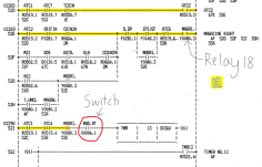
@anglew: Here is a photo of the logic ladder.

Ladder Screenshot.png
I highlighted the completed parts in yellow. The logic seems to be waiting for the part marked in red.
The physical switch is working. With no air pressure on the machine, I can go to the diagnostic screen, find the input address (X0004.1), shove the carousel to the right, and watch the bit flip from 0 to 1. (Perhaps I should check the ladder too just to be sure?)

@SeikiCorp: I found an old program in the control when I bought the machine. Perhaps I should post it here. From my memory, it went something like:

O0001;
(Excel)

>Usual lines for canceling cutter comp, etc.<

M6 T2;

>Main part of program<

G91 G30 Z0;
G28 Y0;
G90;
M30;

I think its rather odd. The "Excel" makes me wonder if it's from another machine. Just for kicks I did try running this in MDI mode:

G91 G30 Z0;
T2;
M6;

The spindle went up, oriented, and then the control alarmed saying the Z axis was not home. I read that sometimes the builder will set M30 to a different height to match the tool changer. Though just by eye, I can't see any difference between G28 Z0 and G30 Z0. Oh yes, and I did run the above old program. The machine hangs on the tool change just the same.

@dandrummerman21: The spindle was having trouble orienting, but I replaced the spindle drive and now it seems to orient fine. You are right, the LEDs are on the PCB, not the relays. The air solenoid for the carousel really could be stuck, but I don't see it's driving relay LED light up either. I would try swapping relays but they are soldered on.

My next idea is to test the whole chain of parts on the machine side: Unplug the M19 cable from the control (this carries the signal to relay 16), power on the machine but not the control, connect 24V DC to the correct pin, and see if the carousel will slide over. If it does then it would seem to be either a software or control board issue.
 
Last edited:
Thanks for the replies.

@anglew: Here is a photo of the logic ladder.

View attachment 385904
I highlighted the completed parts in yellow. The logic seems to be waiting for the part marked in red.
The physical switch is working. With no air pressure on the machine, I can go to the diagnostic screen, find the input address (X0004.1), shove the carousel to the right, and watch the bit flip from 0 to 1. (Perhaps I should check the ladder too just to be sure?)

@SeikiCorp: I found an old program in the control when I bought the machine. Perhaps I should post it here. From my memory, it went something like:

O0001;
(Excel)

>Usual lines for canceling cutter comp, etc.<

M6 T2;

>Main part of program<

G91 G30 Z0;
G28 Y0;
G90;
M30;

I think its rather odd. The "Excel" makes me wonder if it's from another machine. Just for kicks I did try running this in MDI mode:

G91 G30 Z0;
T2;
M6;

The spindle went up, oriented, and then the control alarmed saying the Z axis was not home. I read that sometimes the builder will set M30 to a different height to match the tool changer. Though just by eye, I can't see any difference between G28 Z0 and G30 Z0. Oh yes, and I did run the above old program. The machine hangs on the tool change just the same.

@dandrummerman21: The spindle was having trouble orienting, but I replaced the spindle drive and now it seems to orient fine. You are right, the LEDs are on the PCB, not the relays. The air solenoid for the carousel really could be stuck, but I don't see it's driving relay LED light up either. I would try swapping relays but they are soldered on.

My next idea is to test the whole chain of parts on the machine side: Unplug the M19 cable from the control (this carries the signal to relay 16), power on the machine but not the control, connect 24V DC to the correct pin, and see if the carousel will slide over. If it does then it would seem to be either a software or control board issue.


Before you put 24v to the solenoid to test it, you'd be better off testing for 24v going to the solenoid. if you get 24v, then the solenoid is bad or there's a bad connection. if you don't, then the machine isn't putting out 24v from that relay.


That machine needs a 1 line tool change. 2 lines won't work. You can TRY to put T2M6 instead of M6T2 but it shouldn't make a difference.

What year is this 0? I want to say ours was 1990 or 1991.
 
Last edited:
Hi,

@dandrummerman21:

I think I see what you mean. I actually did check for voltage at the solenoid and the relay a few days ago. Both showed nothing, which is why I began to think the control was not working right.

Good to know about not putting T2 and M6 on different lines. I don't have the machine operators manual and COMPAT didn't either. Thanks.

This machine was made in 1996.

The test:

I powered up the machine but not the control. Found the correct pin on the cable going from the controller I/O board to relay 16. Hooked up my 24V DC, and -nothing. I tried another pin that goes to the tool unclamp relay. CLICK! Works just like it always has. This made me think that maybe relay 16 was bad.

The relay board has 220VAC on parts of it and who knows what will happen if I trip a random relay. So the be safe, I next tried powering off the machine and trying every relay coil on the board with 24V DC. (Power supply + wire to relay coil, -- wire to relay board ground.) Only Three out of the twenty or so relays clicked on. The rest did nothing.

Next I powered up the machine and switched on the control. Two other relays now showed 26 and 40V DC on the coil, but they don't click and neither LED next to them is lit. Strange...

I also noticed that a couple of the relays are in sockets. Neither of these two worked when I tried all relays with the 24v. Just for kicks I pulled out one of the socketed relays and applied my 24v. CLICK! So for some reason, we have a relay that works when off the board, and doesn't when in its socket. Later today I'll try to upload some photos of the relay board.
 
Just a quick question regarding your highlighted ladder. You mentioned the yellow highlighted part was completed; you mean it shows on the ladder page as completed, right? I only ask because you mentioned looking at diagnostic bits to confirm status. I'm assuming that you did indeed see the highlighted ladder lit up on the screen.

Sounds like something's blown or dead. If I understand right, you are missing power to the relays, so I think you gotta figure out where it stops. Whether its a blown fuse, or breaker, or something.


We had a 1993 leadwell MCH400 that had a rectifier die on the main I/O board. It took out a fuse holder and a few runs with it. IIRC my boss who fixed it was annoyed and surprised by how much 240v power they had on the board. He managed to jumper in a new rectifier and several jumper wires to fix that old board.

I am not suggesting that your issue is that serious or complex, just throwing shit at the wall.

I don't appear to have any copies of the mcv0 electrical manual to try to help, they got sent along with the machine when we sold it. Our oldest leadwell is a 1993 mcv1000ar but I don't know how helpful it would be to compare. It's also a swingarm version, no carousel.
 

@dandrummerman21:​

Good question. Yes. I did see the highlighted parts of the ladder also lit up on the control screen.

Funny you should mention having to jumper a relay board. On my machine, the board has had extensive repairs made. There are cut traces, and jumpers running all over the place.

I got a electrical manual from COMPAT. (Thanks guys!) It's relay diagram matches my relay board better than the printed manual that came with the machine. On this diagram, it shows the relay coils are connected via the LEDs. The current has to flow through them to energize the coils. So if the LEDs were bad, then there would be a situation where the relays still "worked" but not when on the board. That's my next idea. Try replacing an LED on relay 16 and see if that helps.
 
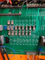
Ok. Here are some pictures:

IMG_0394 - Copy.JPEG

The Machine when I first got it.

IMG_0565 - Copy.JPEG

The relay board. Relay 16 is the last one in the middle row.

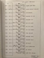
CE - Copy.JPEG

Relay diagram from COMPAT supplied elec. manual (1991). Note the LEDs in line with the relay coils. Also note that the LEDs are on the positive side of the relays. That is one thing I can't figure out. On my board, the same side (EXT +24V at the top of the diagram) is grounded. And it appears the wires from the control supply the positive 24V.
 
.......That is one thing I can't figure out. On my board, the same side (EXT +24V at the top of the diagram) is grounded. And it appears the wires from the control supply the positive 24V.
That picture of the wiring diagram shows a "sinking" I/O. The I/O board providing the ground. Very, very unusual for an Asian machine with Fanuc control. Your description of 24VDC being output by the I/O board is a "sourcing" I/O and is very typical of the vast majority of Asian machines with Fanuc controls. I suspect your diagram is wrong for your machine.
 
That picture of the wiring diagram shows a "sinking" I/O. The I/O board providing the ground. Very, very unusual for an Asian machine with Fanuc control. Your description of 24VDC being output by the I/O board is a "sourcing" I/O and is very typical of the vast majority of Asian machines with Fanuc controls. I suspect your diagram is wrong for your machine.
@Vancbiker:

Thank you! That makes me feel a lot better. I was beginning to think whoever repaired the board last messed things up bad and I'd have to rewire the whole thing.

Hate to be bearer of "bad" news but I'm fairly certain the manual is right.

Looking at the manual of the 1000ar we have, they do the same thing. The 24v is an external power supply. And the LED is drawn in line.

20230204_070417.jpg


I did not poke around the electrical cabinet to compare but I'm confident this manual is correct.


My boss (who is the real machine repair guy at my shop) has told me in the past, that the control on these machines put out "0v" to complete circuits, not 24v. I was not sure why, but it made sense at the time. I'm not positive that this is what he was talking about, though???


Some things leadwell has done in the past has been shown to be questionable, so if this is an oddity or a less preferred method, I wouldn't be surprised.


So with that in mind, you must have a loose honda or bad connection to ground or 0v?


Once you get the 0 running, though, it's a pretty decent machine surprisingly. Nothing fancy, but the machine was nothing but good to us until its last day. Even then, it was simply time. The person who bought it got it just to convert it to some special purpose machine, and basically just needed the spindle to work. No idea what that project was or what came of it...
 
Last edited:
Hey, just noticed, your electrical manual says the relay goes to M19-4 but if I am seeing your board picture right, there's no connector plugged into M19

Am I mistaken, is that little blue honda not M19?
 
This illustrates one of the troubles with trying to help remotely. Since the majority of builders do things similarly, there’s always the oddball that can throw a wrench in the works making troubleshooting difficult.
 
@dandrummerman21:

You are right. That is the M19 connector unplugged. I had it unplugged to isolate the control I/O board while testing with my 24v.

Next time I'm there, I'll get a photo of the back of the relay board. That's where all the jumpers are. One of them connects the traces from the LEDs to ground if I remember right. It's a mess back there. It could be that the best thing to do is remove the board and rebuild it one cut/blown trace at a time. Ouch.
 
Question: Would there be a way to tell if the Fanuc I/O board is sending signals at 24v or if it's the type that grounds an exturnal 24v? My relay board had a trace blow like I said, so perhaps whoever fixed it had to replace the I/O board as well, opting for a different type?

At any rate, the fat traces that join the LEDs together have been cut in several places. Literally isolating them from the rest of the board. There must be 20 jumpers added too. A ton of work for one blown trace. (That was the only damage I saw last time I looked.)
 
What's the part number for the board? We probably don't have it but i could look. None of the ebay boards looked like yours.

Also it is unlikely, but you could ask campat if they have a board. Super unlikely but they occasionally surprise us with parts in stock, and i know that they gave us a price for the mch400 board i mentioned earlier.

Now, that quote was a few thousand dollars and it had to be made (or shipped from taiwan?) and had a 4 month lead time, but we could have bought it.
 
Last edited:


Back
Top