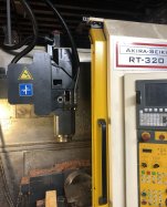
This Akira Seiki RT-320 is a prototype machine from bankruptcy auction. It came with no manuals. I have contacted Akira Seiki to request manuals, but neither they nor any of the Akira Seiki resellers in the US have manuals for any machine remotely similar.
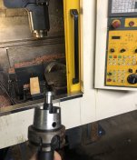
The particular peculiarity with this machine is its spindle: HSK-63 using a pin for retention. Which is insane. I've never heard of anything like it before. That's not how HSK is supposed to work. It should be clamped from the inside, so it presses against the spindle taper. It should NOT be pulled up like cat-40. But, it's a prototype machine, and it cost only $15k at auction.
When the machine arrived at my shop, much of the wiring and all of the pneumatic tubing had been essentially randomly reconnected by unknown people. It took approximately 100 hours of effort to make the machine and automatic tool changer function, again.
I only got approximately 120 hours of spindle time out of it, before the lower spindle bearings failed. I now realize that the spindle is meant to have oiled air going into it. I did attach the air-oiler to it, but it bled far too much air, so I disabled it. What I should have done, in retrospect, is turn down its pressure regulator, so it still received its oiled air but didn't keep my compressor running 24/7.
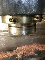
The only indication of spindle manufacturer is a single imprint on the spindle, which says "CAM". That's entirely useless, as a search term.
I have attempted to disassemble the spindle. There is an SC-050 coupling on the spindle drive shaft. With all bolts removed from the spindle motor and the bolts removed from the coupling, and the threaded part of the coupling wound as far down as it will go, 2500lbs of lifting force is insufficient to remove the spindle motor. I'm pretty sure any more force will simply break the Y axis casting.
Has anyone here seen anything like this ridiculous piece of shit? It made good parts, when it ran. I'd prefer to get it running again over parting it out and melting down the 18,000lb casting.


