What's new
What's new

Resurrection of a lobotomised Maho 600T

Finngineering

Plastic
Joined
Oct 14, 2022
I recently acquired a Maho 600T, and thought I'd make a thread about it here. The machine appears to be at least in decent mechanical condition. However, the previous owner had gutted it of the complete contents of the control cabinet as well as the servos. His intention was to renew the controls with the help of a friend, and he bought and mounted new servos, but didn't get much farther than that. He sold the machine "for the price of the new servos and electrical parts" for 2400€. And this is where I pick up.
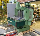
20221013_165710.jpg

I will do the CNC side with LinuxCNC and Mesa motion cards. The servos and drives I got with the machine are not optimal, but I believe I can make it work with them (Leadshine 3000rpm/3.2Nm for horisontal axes and 2500rpm/7.7 Nm for vertical). Fortunately, the optical scales were still on the mill, even though the previous owner had no intention of using them. I will use the feedback from these for proper closed loop control. The main motor is of direct on line type, and as far as I can tell, a step-down autotransformer was used for it in the past to allow slower acceleration for gear changes. This has been scrapped as well, so I will use a VFD for the main motor and of course utilize the gearbox as well.

If anybody knows what the "T" in the model code signifies (Maho 600T), I'd be interested to hear it. I did get the operation manual in German, but if anybody has some other manuals or the proper circuit diagram, I would appreciate if you can share it. The machine serial number is 64096 and the proper circuit diagram would be E-5718. I believe it's from around 1987, give or take a couple of years.

Some more photos showing the condition of the machine.
20220926_171008.jpg20220926_170937.jpg20220926_171108.jpg20220926_171310.jpg
 
Maho 600T is CNC332, which basically is Heidenhain TNC155.
Good thing you have Heidenhain scales, should be easy to put a Heidenhain EXE in between and you get 0.001mm quadrature signal output, directly usable on LinuxCNC

Heidenhain TNC155 unfortunately has SPS/PLC inside, likely what was used for gear switching motors and related logic.
Would at least use some gears with VFD, otherwise no torque at low speeds
Would perhaps do that with a small microcontroller, AVR board maybe, instead within LinuxCNC.

On Dialog4 FP-NC, voltage for 3phase motor is reduced with big resistors and then short spindle motor brake release, until gear mesh up.
Could be perhaps implemented better on a VFD, if VFD is programmed to very low speed, maybe 50-100rpm, it should have equally low torque.
 
The idea is to keep updating this thread as I make progress. But this is a hobby project done in evening hours, so progress will not be that fast. I have a very soft target of getting it up and running still this year.

I plan to use my own converter boards for the Heidenhain scales with the iC-NV chip. In fact, I have already have the parts and PCB here, but have not yet mounted the components and tested it. I will provide more information about that as well after I have tested that it works as intended. It is pretty much the same as an EXE box, but easier to source for me.

My plan for gear changes is to do it with low motor speed through the VFD and have LinuxCNC control everything. If worse comes to worst, I can do the changes manually. But I don't think it will come to that.

I have tested and confirmed some of the auxiliary systems. The central lubrication is working, but there were a few lines where I couldn't get any oil to go. Perhaps because the machine is not moving, perhaps because of something else. I also tried jogging the ram through the servo drive configuration software, and it was working reasonably well. But I noticed that the oil that was pushed out from the ways was slightly brown from corrosion residue. So I made the decision to open up and clean all the ways and ball screws (I probably won't open/unthread the ball nuts). It would be a shame if corrosion and other dirt would wear away the machine just because I didn't bother cleaning it properly. So this is the next part of the journey.

I started by removing the table:
20230228_174020.jpg20230228_175630.jpg

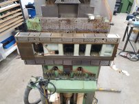
And then went on to remove the X-axis slide:
20230301_202200.jpg20230301_204540.jpg20230301_202244.jpg

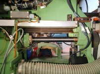
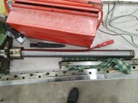
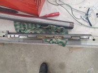
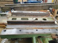
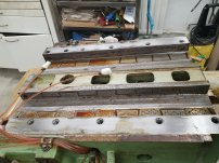
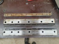
The ball screw and the X-axis gib:
20230301_203517.jpg20230301_203552.jpg20230301_203552.jpg

I haven't checked it very thoroughly, but so far the only real wear I can see it on the outside of the gib. If the rest of the machine is in the same condition, I will be real happy.
 
there is a user on this forum - RotarySMP, he has done basically the same thing, he has a youtube channel, here is a link to summary video of his conversion, there is also a link there in description to another forum (I'm not sure if it is allowed or not to link it, so I won't) containing a lot of useful info regarding the project
he did reuse the original drivers, but it is a minor detail, loop closure is via the HH scales, and I remember he had a video or two explaining the gearbox control logic
 
Yes, I think I’ve seen all his videos on the Maho and most of the others as well. Great content. He and his friend made a LinuxCNC component for the gear box that I presume I can and will use.

I pulled the vertical slide (saddle?) and it’s maybe not quite as good as the x-axis, but still in decent/good condition. I’ll add some photos in the coming days.
 
ThisOldTony is always a fun watch!

Here the continuation. The saddle is coming off.
20230302_175014.jpg20230302_180837.jpg20230302_180846.jpg20230302_181919.jpg20230302_180914.jpg

Can't take off any more large parts at the moment. Nowhere to put them with both carts and all tables full. But the idea was anyway to clean these and put them back together before taking the head / ram off.
20230302_180821.jpg

There certainly is a bit of corrosion, so I'm glad I made the decision to take it apart and clean it. The flaking marks are still visible pretty much everywhere, so at least the wear is less than the depth of the flaking. However deep that is... I might try to measure it before putting it back together.
 
Make sure that the lube metering valves actually deliver. On my AT they were all stuck, but which is unusual.
Note that Vogel has an online shop and some consumables are affordable.
You should buy the AC servos I took off the FP4-60 I parted out. Light, quiet and have grunt. I do not understand why most CNC converters go such tiny toy servos
 
Last edited:
Yes, I was actually checking the central lubrication system some weeks ago. To most places I got oil flow, but there were a handful locations where I didn’t get any. This was also a reason for opening up the ways. I suspect the reason is more with slightly dried up old oil on the ways and not being able to move the axes during lubrication than an issue with the central lubrication itself. It will become clear when I get to cleaning the oil passages.

Compared to the nominal torque of the original servos, the ones I have now are not too far off. Perhaps the old servos had higher peak torque (the specs are a bit unclear). But based on the slip clutch setting for the vertical axis, I expect not. I just hope the low inertia of the new servos don’t cause control loop issues. I will try first with the servos I have. If it doesn’t work well, I have to find something else.

What servos do you have (for sale) Martin P?
 
New/old machine i pretty much replace all the feed checks.
In my experience cleaning old checks of hit/ miss.
Checks are cheap insurance against “maybe”.
Oil is the life blood of any way system
Any machine is only as good as its foundation.
Restoration of any machine needs to
Start with a good foundation.

Clean the oil system, replace the checks and move on to reassembly and upgrading the control.
Need faith that everything downstream is good.

Cheers Ross
 
Last edited:
Thanks for the advice. I certainly have no argument regarding the importance of the oil. New metering valves do not appear to be prohibitively expensive (~500EUR for the machine). But still more than I would prefer to spend on it. I think I will try to test the function of the metering valves I have, and hopefully they all work. I did some basic tests on one of the distributor/header already, and at least without back-pressure, all valves metered the oil. But maybe I have to figure out a way to test them with back pressure as well. I'll give it some thought.

On the subject of central lubrication. Does anybody know how often and how long the pump should be running? This was controlled by the old CNC logic, but I have no idea about how long/often, and don't really see any machine parameters for it in my documentation.
I work for one of Vogel's competitors and generally with PDI oil systems like this I will see common oil delivery intervals any where from 5 to 15 minutes, really depending on the size of the components being lubricated. Since it sounds like you are going to be controlling this portion, I would start off at 5 minutes and observe the oil film left behind directly if possible to determine if you are getting enough. Unless you do the bearing calculations for each lubrication point or find the interval originally specified by OEM your going to have to do some guessing. Hope this helps!
 
A bit of additional info:
Don’t know about Maho but Deckel was worried about the oil film “floating” the slides when running under program.
The lube cycle is inhibited during “feed” moves, and allowed only during a feed hold or rapid move.
Further the feed is held after a rapid until the time of the lube cycle has completed.
Believe the cycle time for the lube pump on the FP_NC’s runs about 20 min.
Believe there are dip switches that modify that time, but to be honest I have never timed the interval.
Length of “on” time of the pump is about 10 sec.
Cheers Ross
 
On the Dialog 11 machines the lube interval is set through parameters 33090 (stationary axes) and 33091 (moving axes).
Since I have the parameters from the parted out FP4-60 right here:
33090 is 14400 seconds = 240 min
33091 is 1800 seconds = 30 min

10 sec run time seems way too long to me. This would only be if pressure is building very slow.
 
It appears documentation about those Siemens servos is not so easy to find online. Based on what little information I can find, I do believe they would be a great fit for the MH600T. And of course the "donor" machine is similar in size. However, like mentioned, I will try with what I have at first. If it doesn't work out and the Siemens servos are still available at that time, we can of course pick up that discussion.

Thanks also for the information regarding the central lubrication. So probably something like every 10 to 15 minutes and running time 10 s should be a safe starting point. I do intend to wire up the pressure switch and generate an alarm if the pressure doesn't build up as "normal". Interesting information about the Deckel philosophy as well. It could be something to consider, but I'd have to investigate if that is doable with LinuxCNC. For my use, I don't think it's necessary, but if it's easily doable, then why not...

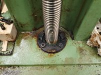
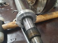
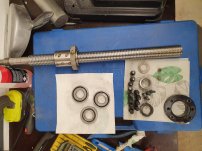
The seals for the vertical axis ball screw bearings were damaged, so I decided to also take the ball screw out.
20230302_191612.jpg20230302_194516.jpg

I marked the orientation of the retaining/preload nut and made a split collar to pull the bearings off (with the force on the inner race).
.20230303_122836.jpg20230303_165642.jpg
As it turns out, the bearings were a slip fit on the shaft and the puller was not needed. Duh.

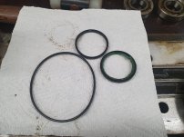
The seals were completely shot and the bearings certainly had their fair share of crud on them.
20230303_165617.jpg20230303_165557.jpg

I cleaned the parts and put new seals (normal lip seals), repacked the bearings with grease and put everything back together. My intention was to remove the ball nut dust seals and flush it out with some fresh oil. But the retaining screws for the dust seals were not budging, and probably loctited in place. So I skipped that step.
20230308_184929.jpg20230308_185844.jpg20230308_192520.jpg

And the screw assembly installed back onto the machine.
20230308_193424.jpg

Cleaning and adjusting the slip clutch is the next step.
 
Now the vertical axis slip clutch.

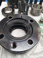
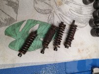
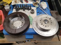
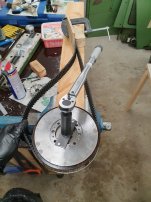
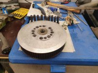
I cleaned it externally and cobbled together a setup to measure the slipping torque. The manual says it should slip at 24 Nm. I measured up to 100 Nm and did not get it to slip. So I decided to take it apart, clean it internally, and readjust it. While it was externally disgusting, internally it was fairly clean. I was not sure if the friction faces should be dry or lubricated. I did put a bit of oil there, thinking it's safer if it tightens up a bit over time rather than loosening up. But I honestly don't really understand why there is a clutch at all. Is there somebody who knows the reason why the vertical axis has a clutch, but not the horizontal ones? Maybe to save the ball screw / nut from too high forces?
20230309_183442.jpg20230309_184330.jpg20230309_192504.jpg20230309_193009.jpg

After cleaning it and reassembling, I modified the setup slightly, so I could easily pull off the belt (no need to have both sides of the belt tensioned). Even with the springs almost loose, I could not get the clutch to slip. I then realized I had tightened the flat bar for attaching the torque wrench through the clutch itself, thus forcing it together. Not my proudest moment. You can see in the first photo the screws were from the side opposite to the torque wrench, and in the following photos where I had corrected this mistake. It was then no issue to set the slip torque to just above 24 Nm. I believe this is quite close to what it was before opening it up as well...
20230309_200904.jpg20230309_200914.jpg

Ready to go back onto the shaft.
20230309_203531.jpg

Not that progress have been fast so far, but it will unfortunately be slower in the coming weeks. I'm travelling for work for the coming 4 weeks or so. Maybe I can find some time to work on the new schematics. But normally travelling also means long days at work...
 
You said the machine did not come with the original servos, but with different servos and drive. What are these?
Which manaul did you find the 24Nm value at?
That is quite a chunky value it seems. But then that disc is huge. I cant quite visualize the component sizes and layout.
 
Don't understand why they would not have overload clutches in all three axis. Guess this was a cost saving measure.
The Deckel FP_NC's have overload clutches (although they are quite a bit smaller than that gizmo) on all three axis..
They are there to protect the machine, mainly against damage from collisions and crashes.


Back
Top