What's new
What's new

rpc out to hardinge dsm-59: transformer

peter9150

Plastic
Joined
Dec 28, 2022
Hi All-new to this forum and need help with final hookup of rpc to hardinge dsm-59. I've plugged rpc in question to my bridgeport j-head to test before trying to connect to my lathe--the concern i have is about connecting my 'clean' 2 legs to the 110 transformer in lathe. From reading that I've gleaned so far: The transformers used to run some 110 circuits within the lathe cabinet need(ie can be damaged connected to generated leg) to be connected to only 'clean' legs.My question:
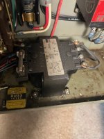
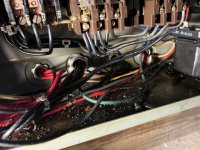
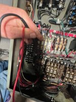
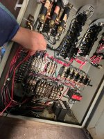
I've traced the 2 lines that coming in that go to the red colored transformer and have the incoming 'clean' legs feeding that transformer. There seems to be a second transformer that i know(understand) too little about to assume turning on power to "see what happens". I'll include some pics--it's the black labeled transformer on the cabinet floor that concerns me.
IMG_1110.jpg IMG_1114.jpgIMG_1109.jpg


Attachments

  • IMG_1113.jpg
    IMG_1113.jpg
    103.3 KB · Views: 4
Thanks for helping..
I have been drying out the print--was coated with oil in the lathe door 'pocket'--sending the full shot here. I could follow the L1 and L3 lines going directly to the 'red transformer' and was hoping to understand (see)how the other transformer was either piggybacking from it or connected also from L1 and L3. I'm green at reading circuit prints (symbols , actually-pretty much dark to all of it) - iIMG_1128.jpg
 
1) I believe the original hardinge schematic has two sections, possibly one old version and one new version. Possible the paper diagram was done in this way to be useable in two different machines in a transition year? There is, I suspect, only one hardinge transformer there, the red one. The black one, based on the smaller fuse size and the somewhat uncertain quality of the wiring, might have been added by a former owner. Can you see if there are any modifications to the machine that might have required another step-down transformer? Extra lights, pumps, receptacles, etc?
 
Thanks Jim,
have tried to check continuity of 'black' transformer on 'bottom' of cabinet -but till now have only done a 'quick' look. But your idea has me thinking--perhaps the placement on the bottom of the cabinet points to the idea of it being an added circuit -hence idea of looking for added pupose (outlets--anything else?-perhaps even a repair?)--will first check for other purposes(outlets or functions)-and then later more continuity checks-some are difficult without power on (with my limited understanding of electrical circuits)
 
Yes Jim---to B1 and B2 wire ends that match that same way-- (not insulated nor crimped ends)at the 'black' transformer--and are probably not an original install
B1 and B2 connect to 'black' questioned transformer--and two (only) lines on this transformer output travel to metal box type enclosure (in pic) next to main motor-I don't know function -(circuit diagram i believe shows powering brake solinoid?)
the original side of B1 on terminal block goes to (pic of fist holding red and black continuity leads) bottom of L1 when pulled"on" contacts (not sure of correct electrical nomenclature) B2 leads run up to (or down from?)taller 'tree' structure -will this fry the solenoid?
 

Attachments

  • IMG_1110.jpg
    IMG_1110.jpg
    54.8 KB · Views: 9
  • IMG_1131.jpg
    IMG_1131.jpg
    115.6 KB · Views: 7
  • IMG_1132.jpg
    IMG_1132.jpg
    157.8 KB · Views: 5
  • IMG_1134.jpg
    IMG_1134.jpg
    79.5 KB · Views: 7
  • IMG_1133 (1).jpg
    IMG_1133 (1).jpg
    89.4 KB · Views: 6
  • IMG_1137.jpg
    IMG_1137.jpg
    67 KB · Views: 7
It would seem that the original wiring had the brake solenoid operated across two of the incoming three phase legs - ie off 240 volts. Did a former owner feel like it should be run off a different voltage?
 
former owner (good friend --closed business-gifted to me this lathe and a bridgeport) is even more electrical blind than myself-so can't answer of helping to understand current layout--I still can't 'see' the power lines into the 'black' transformer in terms of which legs are being used-leg L1 is one connection(B1) but how does the B2 get traced back a leg?to --I may look closer at the brake for more-Thanks for all the help- still finding more good references and prints on this site-I'm green -thanks for the gaps in my ability--any ideas for tracing more to glean better info on what I have?
 

Attachments

  • IMG_1139.jpg
    IMG_1139.jpg
    59.8 KB · Views: 3
  • IMG_1138.jpg
    IMG_1138.jpg
    42.6 KB · Views: 4
Because the brake solenoid may be a problem (may not be connected thru legs 1and 3) I'm thinking of simply trying the lathe without it-simply disconnecting the feed lines to the brake-
 
connected without brake and all seems to run ok-forward, reverse,high and low-would still like to understand better brake connection before connecting -but will run machine as is -used as secondary work station -don't need (for now) for quick changing from forward to reverse--no power tapping
 
Wondering if the black transformer increased, or decreased the brake solenoid voltage? Does the solenoid inside the housing look OEM?
 
Talked with previous owner--never had work that he could remember--but it had been in his factory for 60 years-during dad's 'day'? who knows?-but after you pointed out how it looked out of place-and by looking at wiring diagram (which showed a missing rectifier as well as a missing arc suppressor -am pretty sure not original cofiguration-I plan on using the lathe as is for production for now, with the benefit of testing thr rpc before moving from my garage to the shop---I will take the cover off the solenoid in next week and check out your idea-thanks for your help jim-
 
see print attached--has both a rectifier(bottom right) and an arc suppressor between b1 and b2-same vde-8220 as machine print -not sure still about possible changes--but as you pointed out-the black transformer connected to b1 b2 is not original-and prvious owner when asked about any changes that he was aware of DID SAY that in his memory that whenever he used the lathe that the brake seemed to not work properly--so he would go into reverse if he needed a quick stop
 

Attachments

  • IMG_1146.jpg
    IMG_1146.jpg
    77.6 KB · Views: 7


Back
Top