What's new
What's new

Saved a Hendey from the scrappers yesterday

Means overall length of bed casting - before they decided the customer would be more interested in a between centers dimension as part of the description

Later, Hendey would advertise and mark them such as 16 X 54

Yep, precisionly measured with a carpenters tape measure;), it comes out to 96.25".

On that note, I'm actually having trouble finding keyed shafting for the speed control and clutch engagement shafts along the front of the machine. It seems like most off the shelf stuff is sold in continuous lengths up to 6ft. I need something closer to 8 to replace the shafts with, so I'll either need to do some splicing or make them myself. I'm trying to figure out the set-up to cut an 70" keyway on a machine with maybe 24" of travel (Bridgeport or more likely one of the horizontals). I've done big parts requiring indication between two points, but taking multiple passes to make one seamless keyway may not come out so well. So doing them in two pieces may be better. I can cut the keyed part off of the original shafts and thread and pin the straight portion onto a new 6ft. length of keyed shaft.
 
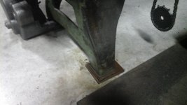
I roughly leveled the lathe the other night with the intent of making the chip pan drain properly. It had a couple extra holes that needed to be plugged but otherwise I can contain the drippings from rinsing stuff out more easily. While I was doing that I noticed something blairingly obvious that I hadn't noticed before:
20160920_175126.jpg
The right leg looks good
20160920_175113.jpg
The left leg is missing feet! Had to pad it up about an inch. So I guess when I strip this thing ALL the way down to fix the ways (someday), I'll have to figure a way to patch it.

Also, the turret lathe I'm scrapping is already becoming an organ donar.
20160920_175147.jpg
Now I've got a decent enclosure for the VFD. The rounded corners should blend in nicely with the rest of the lathe. I'm planning on mounting it on the outside of the left leg. I need to double check the voltage on the transformer, but it should work for a work lamp and any other low volt accesories. The fuse holders are the old european milk bottle kind. I've got them sourced already so i think I'll stick with them.
 
Got the motor finished tonight. It worked fine but was very rusty and dirty, so I poped the caps off, flushed out the grease resevoirs and bearings, media blasted the caps, wire wheeled the exterior of the body, painted and reassembled it. There are a couple ring seals behind the bearings (same as you'd see on a car piston) and I cracked a couple during reassembly. They still pressed into the races though so I think they'll still do their job. Worst case I'll need to keep an eye on the back sides of the bearings when pumping grease in. Luckely the motor frame is laid out so that you can get to both sides of each bearing on each side of the motor.
1477538148476581261749.jpg
14775381936281095376683.jpg
The lifting eye was also added. Details details.

1477538282213579046061.jpg
Also finnished stripping, cleaming, and reassembling the gear train and motor bracket, as well as getting the new motor mounting holes drilled and tapped into it.
 
Major find.... but a let-down

14775385664711656608247.jpg

So this was an unexpected find. A few years ago back in Yoakum, we had a bunch of stuff stored in a rented warehouse across town that had at one time been part of the railroad infrastructure there. I spent many many late nights consolodating everything down into the warehouse we owned next door to our shop. There was alot of stuff left over from previous tenants that we cleared out for the owners, and there was this one closet of sorts that was only accessable via ladder or forklift about 15ft. off the ground. Inside, I found a treasure trove of garbage.... from the 1940's and earlier. Based off the contents and dust, nothing had been taken or added since then. We cleared it out and found all kinds of things from the railroad days. Everything from a vintage hot water heater, to textbooks from the mid 30's, to empty cheap wine bottles. It made for alot of neat antiques to put up around the house.;)

This motor switch was in the pile. After looking at some of the catalog pictures of this and similar model Hendey's, I realized that it was nearly an exact match as one of the pictured switches. But... the catch. The lathe is of course a 3-phase 5HP set-up. This switch is rated for a 2HP 110v motor.:(

So, I've got two option's. 1 I save it for one of my many other restoration projects, or 2, I find out a way to incorporate it into the lathe anyway. Perhaps instead of directly starting the motor (via the VFD), It can activate a contactor that switch's on the VFD. Including a contactor will probably be a better way to go anyway rather than having the VFD directly wired to the service disconnect.

The switch is pretty rough at any rate, but its still very servicable. It's a 2 stage starter with a solonoid trip overload. I can probably gut it and rewire it as a normally open/normally closed switch. It'll need a plexi cover to keep fingers away from the copper plates:crazy:.
 
1478141604013581261749.jpg
The motor is bolted down and I've started the permanent wiring. Kinda working backwards but from the motor the wiring drops down through galvanized pipe and passes through the boss in the chip pan where the original old collet rack and coolant plumbing went. It's definantly going to be safe from impact and flying chips. From there it ties into armored cable that runs into the electrical cabinet (scavanged from the old Czeck turret lathe). The cabinet will hang off the back edge of the chip pan.
14781420205941095376683.jpg
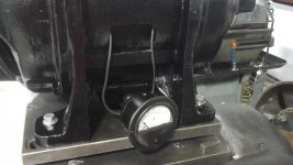
I think I'm going to pass on adapting the old motor start switch and use that space to mount an ampmeter. The one pictured goes up to 60 amps and I only need 20, but it will do for now. The wires run through the case of the motor but are out of harms way in terms of moving parts and such. Once I have the right meter I'll make a sheet metal plate to mount it to that will fill the space between the motors legs. I'm still working out how the vfd will get forward/reverse/stop signal but I've got some ideas. I've got a drum switch that should mount in the electrical cabinet for a master on off switch.
 
1478142581227579046061.jpg
The saddle and crossslide have been cleaned, stripped, and reassembled. Still plenty worn but replacing all the trash with heavy way oil and getting everything assembled correctly has made a big difference. The crossslide screw actually has hardly any wear in it. Once I can get the slide rescrapped it'll be up to Hendey quality.
14781429036361656608247.jpg
That's right! A surface with original scraping fully intact! Granted it's not a critical area, but it still gives ya the warm fuzzies. This was preserved under the paint slathered around the taper attachment. There were some dings I had to stone down, especially along the top edge, but it's all there. Still getting the taper attachment cleaned up, but it'll get back together shortly.
 
20161108_210710.jpg
More progress on the taper attachment. Could use some help with some of the missing/damaged parts though. The anchor for the taper attachment is missing the clamping plate. Should be easy to make but could someone get me a photo of how its suposed to look?
20161108_210936.jpg
Also, the slide casting which bolts to the back of the crosslide is still broken. I'm sure if I'm patient a replacement would turn up, but I think I can mill a patch and braze it all back together. What I need to know however is how long the slot should be? I can figure the rest from pictures I've seen online. Along that same line, the holes along side the broken slot are for a travel stop, correct? Anyone have a complete one and how long is that rod supposed to be? Both of these will of course corespond with the crosslide travel, but I'd like to be sure before I miss something.
20161108_210853.jpg
 
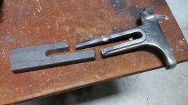
So I started reconstructing the broken taper attachment casting tonight.
148160853110028087074.jpg
Best I can tell, there's about 8" of crosslide travel, so I'm using that as the center to center measurment of the slot.

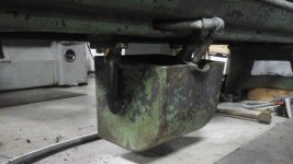
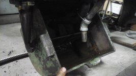
While I was at it, I got those broken brackets for the coolant trough back together. I like the design. It's got a nifty tip action, divider between inlet and outlet halfs of the trough, and is easily remmoved for clean-out.
1481608787276-253835892.jpg
1481608831075-1902322708.jpg
14816088752931995879496.jpg
 
Pics to come, but I've made progress with the drive pullies. We have a decent collection of old line shafting components and I dug up a pair of split flat pulleys that are 14" and 12" diameter and 4.75" wide. Based off of the data I got from Audels Millwrights handbook, I'll need the full 4.75" of belt width to transfer the 5HP between the motor and headstock. The 12" to 14" diameter ratio should drop the top speed RPM to around 1000, which seems to be a safe speed for a lathe of this size, althouh I'll need to stay on the lower end of the range until I can replace that big 4 jaw chuck with something smaller. The motor pulley should mount with little modification, but the headstock pulley is getting a custom adapter to marry the two together, as well as positioning the pulley to better line up with the motor.

The down side is that the belt is going to be very close to any stock that sticks out the aft end of the spindle, but it shouldn't rub unless I manage to cram a bar into the full diameter of the bore. In absence of the original collet draw tube, I'm going to set it up with a 5c collet nose that tightens via chuck key, so ultimatly the only thing that will ever be sticking out of the spindle would be stock.

With the exception of the motor and other related components, you may have noticed I havn't been painting as I've been cleaning and reassembling the machine. Partly thats because I figured it would be better to wait until the major way repairs are done, but mostly its because the "grey iron" look is growing on me. The bare castings have a nice color, and there's no scratches or drips to fret over. Once the cutting oil starts running over everything, I doubt rust will be a concern.
 
The 12" to 14" diameter ratio should drop the top speed RPM to around 1000, which seems to be a safe speed for a lathe of this size

Its a plain bearing Hendey with indifferent head stock lube. It needs to top out at about 400 like Hendey thought
 
Its a plain bearing Hendey with indifferent head stock lube. It needs to top out at about 400 like Hendey thought

Really? Ok I can make that work. Where did they have that information published? Because it seems like with all the threads I found with similar speed-to-bearing questions, discussion kinda fizzled out around the point of "not TOO fast."lol
 
See post #11 Thumbnail - says 418 RPM for 18" 8 speed gear head

There we go. Thanks! I guess I assumed that given the difference in speeds between the 20" and 18", that the 16" would be faster. I see that a 12" pulley is correct as well, which would keep it away from the spindle thru hole. So by my math, to drop the RPMs from 1140 to 418, I would need a 4.4" pulley on the motor I don't think I have one but that's small enough to make out of a solid bar. It would be heavy though. Mabey this would be a good candidate to make a wood laminate pulley.
 
Havn't done alot with this project lately, but after Richard King's scraping class and seeing Steve's planer in action, the Hendey is calling to me!

The class was very enlightening. Instead of seeing 'wear', now I see individual tool paths, lol. There's hope!

1487811176819-1743091291.jpg
1487811213134-330418652.jpg
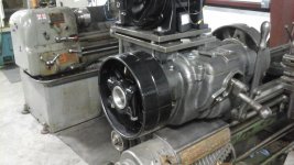
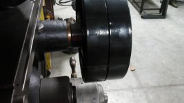
Pics of the headstock pulley. The adapter is 90% done. Last step is to weld on a pair of driving lugs for the pulley halves to assemble around. The rusty cast pieces are the original adapters to clamp the pulley around a straight shaft. The new adapter uses the original woodruff key, washer and nut to mount to the input shaft, as well as positioning the pulley a little away from the headstock to line up with the motor better. Surface finnish is a little poor, but it's a nice fit dimensionally.
1487811537711-1613073037.jpg
1487813348301117529799.jpg
 
More thoughts on the saddle...

Planning ahead:

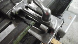
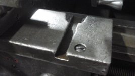
When it comes time to truely fix this lathe (IOW when I own a biax;)), I'm looking at the wear and damage to the top of the saddle. The T-slots seem to mainly be for odd ball set-ups and for mounting things like the coolant plumbing. I still want to keep them fulley functional however, so while the back ones are fine, the front will likely need to have the top lips milled out and have patch plates pocketed in.
1487815863486104248633.jpg
14878159046141082443434.jpg
Before or after this, I want to plane the top surface (I'm talkin' about YOU Steve!). I won't be able to get all the damage out but I should be able to at least get 90% of the surface back and I'll mill a 1/4" radius along the corners to hide the damage cosmeticly.

Now the fun. The gaulding under the crosslide is .025 deep in some places. I'm sure if we plane .005 out it'll bring at least 75% of the surface even, but the worst gaulding is near edge on the chuck side (naturally). So I'm wondering if filling the valley with an epoxy, or even using wear strips, would be the way to go? I'm going to be limited to plaining the same out of the crosslide as I take off the top of the saddle since there isn't much of a height variation between the two.

The crosslide has shifted about 1/8" towards the tailstock due to wear and refitting over the years. If I cut out the exposed portion of the ways on the saddle (removing the shelf for chips to build up on) the gaulding will be exposed from the side, probably making it more difficult to keep any fillers in place. SO, I'm thinking about building up the crosslides dovetail on the chuck side (wear strip?) To shift it back where it originally was covering that lip of the way and leaving a wall of iron to work with when doctoring the gaulding.
148781652987066698350.jpg
 
It's hard to see from the pictures but is the top in two pieces?

You don't have to own a Biax Just buy a few blades for mine and you can borrow it :) ( the only blades I have are too stiff)
 
It's hard to see from the pictures but is the top in two pieces?

You don't have to own a Biax Just buy a few blades for mine and you can borrow it :) ( the only blades I have are too stiff)

Top as in the saddle casting? No its one big H shaped piece. I'm guessing to set it up we would do the 3 point method under the crosslide area and support the four wings with jacks(?).

You're too kind Steve:). I'm ordering some blades in the morning for my hand scraping contraption. First project will be to improve the PPI of that surface plate, then I'll use it to start scraping the ways on my little cincinnati tool and cutter grinder in my garage at home.

Before I get too gung-ho, I'm going to need a couple camel backs with dove-tails. Something in the 18 to 24" range will do most of my projects.

All the surfaces of the bed ways of this lathe are messed up with the exception of those under the headstock, so perhaps referencing the non-bearing flat surfaces would be better to check the flats and V's? Those are chipped and gouged, but more likely less wore than the tailstock ways. I can mabey make a sled that runs on 3 ball bearings: two rolling on one side and a third on the other side. I suppose if we plained the whole thing down, its bound to be 1000 times better than it is now.

IF it's that bad it would be best just to disassemble the bed and plane it.. Use an indicator on the planer to pick up the geometry, plane it, scrape it and then build the saddle and tailstock back up to height. I had to take off .013" to get tom's table straight again.. Sounds like yours is much worse.


Back
Top