Michael Moore
Titanium
- Joined
- Jun 4, 2004
- Location
- San Francisco, CA
This was my first very basic attempt at 3D contouring, and it was complicated by short time frames which required using the cutters on hand, long stickouts with small cutters and general "what should I do next?" newbie issues. I got it done satisfactorily but I'd appreciate some advice on a source for cutters that I think I should have used, and of course any general tips that would have made this easier/faster/more efficient. I did this with my Tree 425 that has a Centroid control and a 6K RPM CAT40 spindle, with air blast and LPS1 in a squirt bottle for chip clearing/lubrication.
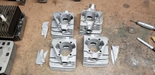
This is for a circa 1970 Yamaha 200 twin that a friend is building up to race. He decided to add another set of transfer ports to the cylinder and convert to a coated aluminum liner. I saved my friend a lot of time/hand work that he would have needed to do after roughing the ports on his Bridgeport. He was able to put that time into the hand profiling of the outsides of the liners and other tasks that needed to be done so the cylinders could meet a deadline for shipping out for nikasil coating and getting back in time to finish building the engines for the first race of the season.
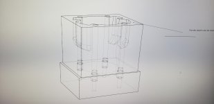
The cylinder bore after removal of the cast iron liner is 2.5". The three walls are vertical from the gasket surface down to about -1.25", then the sides stay vertical as the main wall curves and finishes up at about 1.8" down. The corner radius on the ports is .125". A complication was the bolts holding the cylinder on the fixture were right next to the ports which required additional stick out. To get to the bottom and have plenty of clearance on the ER nut I was using about 2.4" stickout.
As you can see fins were removed by my friend to add weld on the outside of the original (large) port and in the bottom of it (actually the top but I'll label things as they were on the mill) and then the fins were welded back on. The small port was cut into solid metal in the casting with extra metal also added to the outside of that area. With the welding the aluminum was a bit soft/gummy.
I did the upper/prismatic section as 2.5D profile/pocketing. I drilled holes in the corners of the small ports with a 7/32" drill down to the transition to the 3D section, with another hole between those two to rough out a bit more metal. I had a 2.5" LOC 2FL square end EM that I did the initial roughing with, followed by a 5/16" 2FL ball-end mill with 1.7" LOC. The upper section was finished with a 1/4" 3FL sq end EM with 1.5" LOC, and the bottom and corner radii were finished with a 4" OAL 1/4" 2FL ball end mill with .75" LOC.
When finishing the top section I cut an extra .001" off the walls with the 1/4" square EM to try and make a little clearance for the shank of the longer 1/4" ball-end mill. There was still some squeeking going on and rub marks on the shank. I didn't want to cut much more than that and narrow the gasket surface next to the port.
I am aware that SFM at the center of the ball is zero and as the ports were flattening out cutting was taking place closer and closer to the tool center. I don't see being able to get around using a ball-end mill for the pencil tracing in the corner radii, but it seems like the rest of the finishing in the lower section might have been better done with a 1/4" bull-nose mill with a generous (maybe .06") corner radius. If that was also 1/4" diameter then the corner radius would be smaller than the .125" of the ball mill which I think means more of a cusp for a given step-over, but with the cutter extended about 10X the diameter I was using a small step-over anyway.
Other than the pencil tracing in the corners it was all horizontal tool paths. After watching the pencil tracing I'm not sure that vertical parallel finishing in the bottom with a ball mill would have been a good choice, but maybe I should have tried that.
I think it would have been good to have a reduced shank on the 1/4" cutters. I've seen two types, one where the shank is reduced for a short distance above the flutes and then goes back to the full diameter for the tool holder to grab, and the other (which I found at MariTool #1023-.250) uses a full-length 6mm shank above the 1/4" flutes with .625" LOC . I like the latter design as it would allow me to have varying stickouts as needed, but Frank only has that in a square end version in the 4" OAL. He has a 2.5" OAL 4FL with a .02" CR but that wouldn't have let me get to the bottom of the port, plus it is 4FL and not much of a CR and it wouldn't help in the corners.
I called and talked to one of Frank's employees in the hopes that I just wasn't looking in the right spot on the website for a 2-3 FL reduced shank ball mill or one with a large CR, but he said I'd found all there was to find. Shucks.
So what other suppliers have similar ball or CR aluminum finishers with a long slightly-reduced diameter shank? It seems to me like they would be pretty common for working in deep pockets with vertical sides, but that doesn't seem to be the case at the tool suppliers I've looked at on line.
Or is there some other type of cutter I should have been looking for to do that lower finishing operation? I think the "lollipop" type of cutter as used in 5 axis porting of 4T cylinder heads might have had a 3/16" shank for a 1/4" ball on the end and that would be a lot more flexible than a 6mm shank. I did look at one of my porting burrs but that looked pretty iffy.
cheers,
Michael
This is for a circa 1970 Yamaha 200 twin that a friend is building up to race. He decided to add another set of transfer ports to the cylinder and convert to a coated aluminum liner. I saved my friend a lot of time/hand work that he would have needed to do after roughing the ports on his Bridgeport. He was able to put that time into the hand profiling of the outsides of the liners and other tasks that needed to be done so the cylinders could meet a deadline for shipping out for nikasil coating and getting back in time to finish building the engines for the first race of the season.
The cylinder bore after removal of the cast iron liner is 2.5". The three walls are vertical from the gasket surface down to about -1.25", then the sides stay vertical as the main wall curves and finishes up at about 1.8" down. The corner radius on the ports is .125". A complication was the bolts holding the cylinder on the fixture were right next to the ports which required additional stick out. To get to the bottom and have plenty of clearance on the ER nut I was using about 2.4" stickout.
As you can see fins were removed by my friend to add weld on the outside of the original (large) port and in the bottom of it (actually the top but I'll label things as they were on the mill) and then the fins were welded back on. The small port was cut into solid metal in the casting with extra metal also added to the outside of that area. With the welding the aluminum was a bit soft/gummy.
I did the upper/prismatic section as 2.5D profile/pocketing. I drilled holes in the corners of the small ports with a 7/32" drill down to the transition to the 3D section, with another hole between those two to rough out a bit more metal. I had a 2.5" LOC 2FL square end EM that I did the initial roughing with, followed by a 5/16" 2FL ball-end mill with 1.7" LOC. The upper section was finished with a 1/4" 3FL sq end EM with 1.5" LOC, and the bottom and corner radii were finished with a 4" OAL 1/4" 2FL ball end mill with .75" LOC.
When finishing the top section I cut an extra .001" off the walls with the 1/4" square EM to try and make a little clearance for the shank of the longer 1/4" ball-end mill. There was still some squeeking going on and rub marks on the shank. I didn't want to cut much more than that and narrow the gasket surface next to the port.
I am aware that SFM at the center of the ball is zero and as the ports were flattening out cutting was taking place closer and closer to the tool center. I don't see being able to get around using a ball-end mill for the pencil tracing in the corner radii, but it seems like the rest of the finishing in the lower section might have been better done with a 1/4" bull-nose mill with a generous (maybe .06") corner radius. If that was also 1/4" diameter then the corner radius would be smaller than the .125" of the ball mill which I think means more of a cusp for a given step-over, but with the cutter extended about 10X the diameter I was using a small step-over anyway.
Other than the pencil tracing in the corners it was all horizontal tool paths. After watching the pencil tracing I'm not sure that vertical parallel finishing in the bottom with a ball mill would have been a good choice, but maybe I should have tried that.
I think it would have been good to have a reduced shank on the 1/4" cutters. I've seen two types, one where the shank is reduced for a short distance above the flutes and then goes back to the full diameter for the tool holder to grab, and the other (which I found at MariTool #1023-.250) uses a full-length 6mm shank above the 1/4" flutes with .625" LOC . I like the latter design as it would allow me to have varying stickouts as needed, but Frank only has that in a square end version in the 4" OAL. He has a 2.5" OAL 4FL with a .02" CR but that wouldn't have let me get to the bottom of the port, plus it is 4FL and not much of a CR and it wouldn't help in the corners.
I called and talked to one of Frank's employees in the hopes that I just wasn't looking in the right spot on the website for a 2-3 FL reduced shank ball mill or one with a large CR, but he said I'd found all there was to find. Shucks.
So what other suppliers have similar ball or CR aluminum finishers with a long slightly-reduced diameter shank? It seems to me like they would be pretty common for working in deep pockets with vertical sides, but that doesn't seem to be the case at the tool suppliers I've looked at on line.
Or is there some other type of cutter I should have been looking for to do that lower finishing operation? I think the "lollipop" type of cutter as used in 5 axis porting of 4T cylinder heads might have had a 3/16" shank for a 1/4" ball on the end and that would be a lot more flexible than a 6mm shank. I did look at one of my porting burrs but that looked pretty iffy.
cheers,
Michael