What's new
What's new

Should it spin by hand? Hrt servo

After sleeping on it, I have two thoughts:
  1. Is the missing thermostat hot lead the issue?
  2. Could the home sensor be the issue? I have not checked it yet and I don't quite understand how it works. It's got three leads.
@magno_grail - how did you test the home switch when working on your friends HRT9? Looking at your post with the 14-pin connections, I don't think I see the home sensor in there. Also, I do have a brake. I don't have air pressure on it right now, just to remove that as an issue.

Also - do you know the formula to unlock the parameter protection through parameter 30? I found a formula, but it seems to be for a more modern unit (e.g. multiply by 1027, convert to hex...)
 
Last edited:
A two wire home switch is a magnetic reed switch. You can check it with an Ohm meter and turning the home magnet past it. If it is three wires then it is a Hall effect switch, probably with red, black and a third colour. Apply 5V to the red/black and a resistor between the third and +5V. measure across the resistor or the wire to ground. A Cherry Hall switch uses Brown/Blue/Black instead of Red/Black/Other. Check the wiring to see which are the power and signal. The pull-up resistor can be 500 - 1K Ohms.
The 14 pin does not have a Home wire unless you change the cable wire and the connector inside the machine. The 14 pin rotary homes on the Z channel.
My Settiings uses 37 Parameter Lock. Change it to 1 to unlock. Setting #30 is the 4th axis Enable.
Fault #138 is A motor Overheat. I am fairly certain the switch is NC so if the connection breaks it is the same as the switch opening.
There is an Air Brake Parameter in the A servo common switches.
Check your diagnostics for the thermo switch. You can invert the thremo switch in the A Common Parameter.
 
A two wire home switch is a magnetic reed switch. You can check it with an Ohm meter and turning the home magnet past it. If it is three wires then it is a Hall effect switch, probably with red, black and a third colour. Apply 5V to the red/black and a resistor between the third and +5V. measure across the resistor or the wire to ground. A Cherry Hall switch uses Brown/Blue/Black instead of Red/Black/Other. Check the wiring to see which are the power and signal. The pull-up resistor can be 500 - 1K Ohms.
Thanks - I'll give it a whirl. The three wires on mine are red/black/blue. What wattage would I need for the pull-up resistor?
The 14 pin does not have a Home wire unless you change the cable wire and the connector inside the machine. The 14 pin rotary homes on the Z channel.
I'm working on a HRT9 that probably dates from the early 90s and it has 14 pins. There are definitely the 3 wires (red/black/blue) that go inside of the platter and that's why I'm thinking there is a home switch/sensor. If you look at the 2nd picture in this post (Post link), you'll see the red/black/blue wires (the black wire is hard to see) disappearing into the platter below the motor. The wires run through the 14-pin cable, but maybe they were added later?
My Settiings uses 37 Parameter Lock. Change it to 1 to unlock. Setting #30 is the 4th axis Enable.
Fault #138 is A motor Overheat. I am fairly certain the switch is NC so if the connection breaks it is the same as the switch opening.
There is an Air Brake Parameter in the A servo common switches.
Check your diagnostics for the thermo switch. You can invert the thremo switch in the A Common Parameter.
Yep, OK. I read a post that you had been using a buddy's HRT9 and so I was trying to refer back to that. Sorry for the confusion. Do you know the formula to remove the protection on these old machines?
 
500 Ohm across 5V is 1 ma so 1/4 Watt is plenty.
Haas electrical diagram shows home switch connects to pin D.
BrushMotorWiring.jpg
Not sure what protection you mean. I only have a parameter lock. Do you mean to unlock software features? I do not have any information on that.
 
500 Ohm across 5V is 1 ma so 1/4 Watt is plenty.
Haas electrical diagram shows home switch connects to pin D.
Thank you. Of course. V=IR. I'm still coming up the learning curve on some aspects of electricity.
Not sure what protection you mean. I only have a parameter lock. Do you mean to unlock software features? I do not have any information on that.
I think it must be what you call Parameter Lock. In my manual, it is called Parameter Protection. Parameter 30 gives a random 5-digit number. To unlock the parameters, one needs to apply a formula to that number and type it in, which temporarily unlocks the Protected Parameters. Then I could go into Parameter 24 and permanently unlock (unprotect) all the parameters. If you don't know, no worries, I'll go to Haas. They just don't seem to have much support on the older models.

Thanks for the wiring diagram as well. That's awesome! I note that the diagram is a 17-pin while mine is a 14-pin. It looks almost the same as mine except that I only have a single A,B, and Z. I'll need to go back and confirm whether the Pin letters line up. My encoder wiring looks like this (below) which you posted some time ago, but I have a brake and the Hall Effect Sensor like the diagram you just posted. My encoder Pin letters line up as well with the diagram below. 5C_cable_Orig w 14-oin out and encoder.jpg
 
Last edited:
The main difference between the 14 and 17 pin is the encoder is only A,B,Z (TTL output) on 14 pin and A,A/,B,B/,Z,Z/ (differential output) on the 17 pin. Pin D used for Home, H,M used for Brake, L used for Temperature on 14 pin.
Are you sure you mean Parameter 30, not Setting 30?
Parameter 30 is Z axis P gain. Setting 30 on mine is the 4th axis enable. Setting 7 is Parameter Lock. Not permanent, only for as long as the machine is powered up.
 
Are you sure you mean Parameter 30, not Setting 30?
Parameter 30 is Z axis P gain. Setting 30 on mine is the 4th axis enable. Setting 7 is Parameter Lock. Not permanent, only for as long as the machine is powered up.
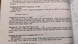
Here's a page from my Haas HRT 9 manual. Take a look at how Parameter 29 is (PROTECTED!). Parameter 30 is value that needs to be fed into a formula in order to unlock/unprotect the other parameters.


HRT9 Parameter 30.jpg
 
Those are parameters for the HRT 9 controller. I do not have one, my 4th axis is directly connected to the VF-1
Well I'm glad that our respective machines have similar wiring at least. I have a request into Haas on the formula. This is what I found in my search for the formula:

Parameter 30 times 1027, then convert to hexadecimal, then invert the last 2 pairs to the right of numbers, (ie: if you end up with 1b52 then make it 521b) then take this number and convert to decimal, then type the result into parameter 30. Immediately go to parameter 24 and subtract 8 to keep the lock off.

This doesn't work in mine because i only have a 5-digit space to type in the resulting number. I've tried dividing the result by 1027 and entering that number, but it didn't work.
 
Good luck getting Haas to give you the formula. That is how they make users pay for options and since they do not support the older software they will likely suggest you upgrade to the latest which also needs brushless servo motors. So basically the entire computer hardware and probably the spindle drive, around $30K or so?
 
I have a positive update. I've made progress, though I'm not quite there yet.

  1. I confirmed that the Home Switch is working, following magno_grail's advice above. I see a change in the readings (both Voltage and Resistance) from the Hall Effect Sensor third wire at only one point in the rotation. There is a machined 1/8th dimple on the surface of the table and the change in reading occurs when that dimple is at the bottom of the circle.
  2. I confirmed that the thermostat is working, using a heat gun. It is a Pepi CR thermostat and I found that CR units are normally open, so the fact that one of the wires isn't connected to the MOBO in the Servo Control should not be an issue.
  3. The one that gave me a step forward - I found a broken wire to the air brake inside of the long cable between the Servo Control and the table. Luckily it was right at the connector that plugs into the back of the Servo Control. Once I repaired the wire, things started behaving differently.
Things still aren't quite right but now:
  1. I no longer get a Ser Err at all. Before I was getting either Ser Err or EncodEr when I tried to home the table or move it by jogging it. Now I only get the EncodEr error. I believe this is because I fixed the broken air brake wire.
  2. I hear the air brake solenoid opening and closing when I jog the table or attempt to Zero Return (Home). Same as immediately above.
  3. I also adjusted the parameters so that the display now shows 4 degrees of table movement for each rotation of the motor, which makes sense since the worm gear ratio is 90:1.
The remaining issue is that I continue to get an EncodEr error when either trying to jog the table or use Zero Return (home). Zero Return is necessary to get everything going. After each time I receive the error, I hit Cycle Start to reset the error. I've noticed that when jogging the table, the motor shaft always turns exactly 360 degrees, triggers the EncodEr error, and stops at the exact same location.

I feel like I'm really close here. The Servo Controller knows the number of degrees the table has turned as a function of the data it is receiving from the encoder. It has to be reading the encoder. Still, something is not quite right. I'm going to talk to the company where I purchased the encoder tomorrow. They said they'd help me once I got things set up. I hope to hear back from Haas tomorrow too.
 
Last edited:
Very cool info/reading on this thread.
I wonder if I can edit the name to more appropriately reflect the info you fellas have put into it?

Keep posting. I wanna see all the results!
 
Very cool info/reading on this thread.
I wonder if I can edit the name to more appropriately reflect the info you fellas have put into it?

Keep posting. I wanna see all the results!
Thanks for the support! ...and for the continued hijack of your thread - haha. Looking forward to seeing the end of this one!
 
Thanks for the support! ...and for the continued hijack of your thread - haha. Looking forward to seeing the end of this one!
Total hijack! Haha
As long as good I for is being exchanged I’m a happy camper :)

Good to know how to repair our own things for those of us that have more time than money!
I was happy I had a spare servo from a auction bundle, got me back up and running g in under a day.

I’ve had to repair lots on my machine but never as deep of a dive as your going. Beyond me technically.
 
Success! It works! I talked to someone from the local Haas shop who was really helpful. He took the time to help me reset my Servo Controller for the HRT9. It should have already been set up, but who knows. I'll take it. So, my repairs all worked.

First, he had me first unlock the parameters, which is what I was talking about before. He didn't have a formula, but a program. I read him the number from my Parameter 30, then he input it into his program and it spat a number back out. I entered that which allowed us to turn off the protections so we could change all the parameters. We started from scratch and input all 37 parameters. The only info he needed from me was the encoder resolution - 500 line.

After that, just about everything worked the way it should. However, when the motor accelerated really fast, or turned at a very high speed, like when I tried to send the table to the home location, it would error - Ser Err. He showed me a few parameters that I could play with to reduce the top speed of the platter rotation and also the acceleration rate. He said it was asking more of the motor than it could deliver. I wonder if there's some gooey oil in the table that's making things more difficult.

I still have some work to do. I need to change the oil and put the motor box back together and seal it up well. I tested the brake with air, and it's holding air, but I'm not quite sure it's doing the right thing. I can hear the air pressure building up and releasing, but when it releases, no air is coming out of the exhaust pipe. I can't really tell if the brake is locking the platter, either. I'll figure it out. I also need to repair the membrane keypad on the front of the controller. All the keys work, but 3 of them need to be pushed really hard to function. I may also rebuild the 14-pin cable. It's pretty ugly and I don't want anymore broken wires in the future.

So, finally, I've got it working and now it's down to cleaning it up and making it pretty and reliable.
 
I finally have an update. I've been cleaning up the electrical box. At least 3 of the keys weren't working unless I pushed on them really hard, which was annoying, and they were pretty dirty. Here's the before shot. I snapped it as I was trying to remove the keypad. FWIW, it slides out of the pin connectors on the front circuit board easily, and you also need to grind off the plastic mounting studs at the four corners.

PXL_20220913_181935925.jpg

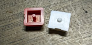
The keys were falling out of the pad. I could have bought a new one from Haas for $145, but what fun is that, so I printed new keys with my 3D printer. They look good enough for the workshop. Old is on the left, new is on the right. The bumps in the white are an artifact of the white trying to print around the number 2.

PXL_20220930_164726045.jpg

The little nub on the back is what contacts the trigger pad. These were broken off on three of the keys.
PXL_20220930_164501186.jpg

I reprinted the white keys so that they would all look the uniform, but was able to reuse the red ones.
PXL_20220930_212806622resize.jpg

And finally together. It's better than a 5 x 5 paint job and it actually works as intended.
PXL_20221001_040702994.jpg

I'll be mounting the keypad on the servo control box tomorrow and closing it up. I still need to rebuild the cable and close up the rotary table. I have new wires, conduit and gasket material to do the jobs.
 

Attachments

  • PXL_20220913_181935925.jpg
    PXL_20220913_181935925.jpg
    862.1 KB · Views: 2
The box came together nicely and I also rebuilt the cable using new, more flexible conduit. The old conduit was like a hula hoop.

ERDZS1wXnNKwugOu5pXAPIs0QX4q7pEwqC3GAZZzSJxbPpzAOgxi6U1Of9twpoDYvaAIT312H4ksaW1oTUQukDY_XPVa1wJEsohsOIPbTfaPl87uRLu6lTsAmbsp3hP--k9lx_8MXZY=w2400


UuA3UCZXV4JPXGi4f8v0lfXDNLkrgP6WQvuOewjAd_OmvmA7Kn97s8u7b6aKTpbuhyev_8OShqpAACTnhgezdWpKXtGSDxlQrhJs-0BKHyI8E2eh19vfenngQrla9im-c4cMINVpu1Y=w2400


C43YTt7CVjqbiFGktENZEv6tPh5jcg2Estmai44-G9aR0qLKJIr_w3gn4oMzCer30k_yxcfucUG2UCbSBfId5Q898Ikiz-VnUgOK-5nRCUBgBOawvG44i3qXYq7MDVzdF1a1IyE44_I=w2400


vs_H9-PQ_dN4QlrsocqmemLcSnHpMts9mj4r2WvdUWpsiCYZqFrRtjLn9lnFd9oj7CqS5MEYy7GsdHqLej6eSkBNO9If1lwXc-RCtYxd-0xWMbP7n9axiggCEFJjncU-7zl98f1GHP8=w2400


E41Z9BaHX2tiWm8CQO1JN5IfB3NcgLLjCbna0tyil7e6t_X9PkYnQqcSDdHtdZRLarNPoYIIPQpgIEbqNLX1RIzuVAXeUw__4tsOM5DpR1oGooGgmdfesrb457D7KK9OYXZfZqm9LB8=w2400
 
And, it's done. Everything is clean, reassembled and working, for now. Fingers crossed. I ended up having to print the keypad frame, in addition to the white keys as mentioned before. The original was fatigued from removal.

I don't have the air hooked up in the video, but it does work. The repeated clicking is the solenoid for the air brake, which triggers at the beginning and end of each movement. You can just imagine the hissing sound when the air vents. Time to make some parts, finally.

 
Last edited:


Back
Top