Simple trick to keep you from getting confabulated when doing miter cuts. Didn't want to post in SolidWorks thread because it's a tip that's good across a lot of programs.
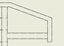
Say you want to build this shape out of tubing.

So cool, lets throw an angle dimension on it.
Ok poop salad. It's trying really hard to crap out a supplementary angle set, and is extremely touchy. We're after a complementary angle, which is what the protractor on your saw or a speedsquare will give you. Sure a little arithmetic could solve it, But why fight it..

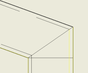
Do this simple thing. Sketch between the corners, point to point, just like your fitup would look like. The square line I'll get to in a sec..

Now dimension it thusly..Here's your saw angle.

For an added layer of sanity checkage, pull a dimension on the "A" side of the triangle. You don't even need a fancy angle measuring tool to get a precision angle layout this way.

Dunno if this was helpful, since a lot of people here are already pretty mathematically inclined. At the same time I've seen dudes on jobsites get spun out trying to figure out the methmatics on anything that isn't a 22.5/45/90. But this is just one little thing about CAD that annoys me, and this little workaround has helped. Saving time and reducing the chance of error!
Say you want to build this shape out of tubing.

So cool, lets throw an angle dimension on it.
Ok poop salad. It's trying really hard to crap out a supplementary angle set, and is extremely touchy. We're after a complementary angle, which is what the protractor on your saw or a speedsquare will give you. Sure a little arithmetic could solve it, But why fight it..

Do this simple thing. Sketch between the corners, point to point, just like your fitup would look like. The square line I'll get to in a sec..

Now dimension it thusly..Here's your saw angle.

For an added layer of sanity checkage, pull a dimension on the "A" side of the triangle. You don't even need a fancy angle measuring tool to get a precision angle layout this way.

Dunno if this was helpful, since a lot of people here are already pretty mathematically inclined. At the same time I've seen dudes on jobsites get spun out trying to figure out the methmatics on anything that isn't a 22.5/45/90. But this is just one little thing about CAD that annoys me, and this little workaround has helped. Saving time and reducing the chance of error!

