What's new
What's new

Small punch milling for horology

J Grainger

Cast Iron
Joined
Oct 12, 2006
Location
United Kingdom
I'm eventually looking at making a punch for watch hands, probably to make less than 100. I could do with making a few watch hands and would like to use the punch milling attachment for my deckel, hence milling a punch and die, as much for my own sense of achievement as anything.
The hands will be carbon steel around .010" in thickness, possibly a couple from the same thickness in brass.
It looks like the die is made in 3 parts, with 2 forming the base, hardened and used as a template for the punch via a coating of solder then bringing together to leave the shape on the punch to be milled.

Would I be right in thinking that the die has the relief, and the punch is just straight?

For the intended use, realistically how hard do the die and punch need to be?
I was thinking of either using an air hardening and/or pre-hard steel.

Thanks,
Jonathan
 
It sounds like the task is for fun and education?
So you don't have to exactly replicate ancient industrial methods.

I've made lots of simple punches from hardened, usually M2 steel blanks or busted endmills and such.
Only a few with mating dies, for simple things.

It does make sense for a complex shape to make the die first.
Especially since for watch hands there is presumably some slight wiggle room on absolute dimensions?
I don't like split dies, because then you have to make a holder. But it is a good way to make symmetrical parts: Mill or form grind a longish stick, cut in 1/2 lengthwise, and place the parts face-to-face. Grind the parting face(s) if necessary. You can even add relief across at least the width, by how the faces are ground. There could be reason to put the relief in the punch, instead, even though it means you have to drive a part all the way through the die. So long as the cutting end of punch itself is not dragging (too big). Grinding relief in the punch is easier to tweak (than tweaking a die) with slipstones. And then to grind the end (length) a little bit if necessary, until the size just slips in the die. If the shank will fit through the die, blue can be used to mark as you creep up on the fat end.

I suppose that if you do make the punch from normalized stock, when it is close, you could hob it (press it through the assembled, hardened die)

For small parts with thin sections, so far i prefer to grind from the solid, hardened stock. Saves all kind of risks in HT and follow-on ops. But i have not yet made something as potentially complex as you might be envisioning.

smt
 
I’m thinking anything more complex than an arrow would be better electrochemical etch or whatever it’s called, mask then etch the part, a friend used to make ornate ones with a Taylor Hobson pantograph ( I have the engraving machine in the back of the shop) I have seen some hand dies and punches , they were cut on a die shaper thing , beautiful how the punch is shaped by these machines, cool, seen some videos on the YouTube somewhere, I’ll have a dig, vertical punch shaping machine, it was like a slotter had a fling with a rose engine
He often hand made the things, riffler files and patience
Mark
 
Thank you for replying.

In terms of context, one of my hobbies started as watch repair, and is progressing towards watchmaking by traditional methods (was doing some of the repairs such as boring and bushing pivot holes with a 8mm lathe and faceplate, making the occasional wheel, etc, and decided I might as well just admit I was trying to avoid the task of just making watches and cases from scratch). I've done some paid work as a machinist, mostly manual turning, and it's also a hobby.
This press tool is mostly for the satisfaction of having made it - I could make a few hands without one if it was necessary.
I realise that nowadays there's photo-etching and EDM.. crucially, I can't program and don't want to make the headspace to learn modern methods - particularly being better with my hands than using modern technology.. I've got a Taylor Hobson K as it happens - will end up using that to mark out some cliché plates for etching, to pad print a dial (did look at vector art in order to send that out but it would take me ages or cost money for someone else to draw up while being less satisfying).. All these projects are a bit as a time around shifts/gf/etc, in my spare time and basically prioritised by whatever order entails the least manual lifting and tramming of machine accessories. Tbf, even one-off hand-made is a potentially doable business in horology - if it came to that.

For the die and punch, it sounds like 0.3-0.6⁰ is ideal for a relief angle.. part of the reason I ask about which part needs it is that it would be easier to just put it on the die.
Some time ago I also remember reading that a punch can be somewhat soft, and effectively mushroomed in order to take up a bit of wear.. but I'm thinking that might not apply here. I also remember someone saying they used some soft tools for occasionally stamping in soft precious metals.
As to using a split die, provided it's ground or lapped flat on the top and bottom, it probably won't require a lot of clamping force for something as small as a watch hand, and it seems the only way of machining a .005-.025" wide slot which is pointy at one end.. could even make asymmetric wavy hands..

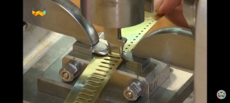
Below is a screenshot from YouTube, there's a pilot/lead projection for the stamped holes.. it seems to be the exact sort of setup I've read the punch milling attachment was intended for, and is being used for minute hands. A 2nd stage could possibly be used for forming the boss on hour hands.. this is part of my inspiration for the project and a sign that it must be doable.


Screenshot_2023-01-05-12-22-13-165_com.google.android.youtube.jpg
 
For your application, I would make the punch first. You could go either way, hardened tool steel (D2, or M2) ground to the shape you want, or machined and hardened then finished.

Then, find a die set that is very rigid and accurate, and produce a die section from W1, or O1. Mount the die section and dowel in place.

Fashion a punch holder and find a way to secure it to the top half with dowels and screws.

Install the punch in the top and bring the two together and scribe the outline of the punch onto the die section.

Then, mill out the center , leaving the lines. I know for this project, the endmills will be dainty, so if you could get down to 1/16 deep that should be fine.

Flip the whole business and mill from the back to create slug clearance. Leaving the 1/16 land at the top.

Assemble the die and shear in the punch to the die section, using lots of cutting oil, often.

When your thru the land portion of the die section, flame harden the cutting edges of the die with water or oil.

Sharpen the punch and the die without disassembling them

Don't worry about tempering the die.

Old school die making class....dismissed.
 
I was taught, bucket of water, hand in water holding the bit you want to harden poking up, heat with oxygen acetylene , once hot, drop your hand to quench, works like a dream not very scientific! Shop heat treatment!
I have the pantograph with the round trumpet looking stand, model M perhaps, one of the earliest I beleive.
It’s remarkable how a bit of Perspex can make a nice pattern, 3D printed are better I’d reckon , fascinating I’ve got too many interests tbh.
Was donated a high speed bench drill recently, from a clock works originally ( smith’s instruments in Swansea)
Sticking a 12 thou hole through 1/4 steel no problem, I found it quite exiting!
Mark
 
Hi J Grainger:
I am neither a watch maker nor a professional diemaker, but I have made a reasonable number of punch dies for tiny prototype parts and I know how to do basic Google searches.
A couple of things about punching thin skinny parts...I've found that the thinner the part, the fussier and more consistent the die clearance has to be to get a good clean part without bends, burrs and tears.
Also, the smaller the die clearance, the more accurately the die needs to be built so the die doesn't self destruct by slamming the edges of the punch into the edges of the die section.
Your maximum die clearance for the thickness of steel you intend to punch will be close to 0.002", so there's not a lot of room for misalignment between punch and die.
If that die clearance is not very consistent, there will be areas that won't shear correctly, and the part won't come out very flat or you'll get areas that didn't shear at all.

Also, the narrower the part is in relation to its thickness, the more demanding it is that you get the die clearance just right all around the periphery of the part.
Incidentally, it also matters that the edges of both punch and die section are perfectly sharp with zero defects like chips or rolled edges...defects like these are fine on punch dies for an ironworker, but not for what you want to make.
You must also have positive relief all around the die land...zero draft is theoretically OK but only if it is perfect everywhere.
If you have half a degree of die relief, there is less of a need to have the angle exactly the same everywhere so long as there is some relief everywhere on the die land.
An area of negative angle or a convex die land is the kiss of death for the die.
So I wire EDM all the punches and dies I build, just to be able to control the geometry easily.
If you don't have access to that tech, you have to know to be careful to get the die land as perfect as you can make it and zero or positive relief is part of that perfection.

The next part is the Google part:
Here's a link to a video and text, showing some of the steps in making watch hands:

One of the things the text points out, is that the hands are friction fit onto the cannon pinion, and this is done by first putting a precision hole into the center of the watch hand and then locally deforming the metal around that hole to form "canons".
As you can imagine, you need to get this part dead nuts accurate or the hands won't be able to be mounted to the cannon pinions.
Also, according to the text, those pinion bores are put in first, before the outline of the hand is blanked.

Speaking of "blanking", there is a process called "fine blanking" for making sheet metal parts that is different in detail from punching, in that the metal is basically extruded through the die section while being supported on both sides rather than being sheared with a punch.
It does not appear, from the few details shown in the video, that this process is being used...the dies look like standard progressive dies to me, but I don't know if fine blanking is needed for certain hand designs, and if they're just not revealing those details to us.
Die clearance for fine blanking is tenths.

So what you hope to do is a pretty tall order.
Now obviously the watchmakers of old did manage to do it without split tenths grinders and Diaform dressers, and wire EDM machines, but my gut tells me it's not going to be an easy road, so expect to be at it for a while before you find success.

The details of what the geometry needs to be I will leave to others with more diemaking and watchmaking experience.

Cheers

Marcus
www.implant-mechanix.com
www.vancouverwireedm.com
 
Last edited:
For your application, I would make the punch first. You could go either way, hardened tool steel (D2, or M2) ground to the shape you want, or machined and hardened then finished.

Then, find a die set that is very rigid and accurate, and produce a die section from W1, or O1. Mount the die section and dowel in place.

Fashion a punch holder and find a way to secure it to the top half with dowels and screws.

Install the punch in the top and bring the two together and scribe the outline of the punch onto the die section.

Then, mill out the center , leaving the lines. I know for this project, the endmills will be dainty, so if you could get down to 1/16 deep that should be fine.

Flip the whole business and mill from the back to create slug clearance. Leaving the 1/16 land at the top.

Assemble the die and shear in the punch to the die section, using lots of cutting oil, often.

When your thru the land portion of the die section, flame harden the cutting edges of the die with water or oil.

Sharpen the punch and the die without disassembling them

Don't worry about tempering the die.

Old school die making class....dismissed.
Thank you, that's some useful information - either for this or a later project
 
Last edited:
Hi J Grainger:
I am neither a watch maker nor a professional diemaker, but I have made a reasonable number of punch dies for tiny prototype parts and I know how to do basic Google searches.
A couple of things about punching thin skinny parts...I've found that the thinner the part, the fussier and more consistent the die clearance has to be to get a good clean part without bends, burrs and tears.
Also, the smaller the die clearance, the more accurately the die needs to be built so the die doesn't self destruct by slamming the edges of the punch into the edges of the die section.
Your maximum die clearance for the thickness of steel you intend to punch will be close to 0.002", so there's not a lot of room for misalignment between punch and die.
If that die clearance is not very consistent, there will be areas that won't shear correctly, and the part won't come out very flat or you'll get areas that didn't shear at all.

Also, the narrower the part is in relation to its thickness, the more demanding it is that you get the die clearance just right all around the periphery of the part.
Incidentally, it also matters that the edges of both punch and die section are perfectly sharp with zero defects like chips or rolled edges...defects like these are fine on punch dies for an ironworker, but not for what you want to make.
You must also have positive relief all around the die land...zero draft is theoretically OK but only if it is perfect everywhere.
If you have half a degree of die relief, there is less of a need to have the angle exactly the same everywhere so long as there is some relief everywhere on the die land.
An area of negative angle or a convex die land is the kiss of death for the die.
So I wire EDM all the punches and dies I build, just to be able to control the geometry easily.
If you don't have access to that tech, you have to know to be careful to get the die land as perfect as you can make it and zero or positive relief is part of that perfection.

The next part is the Google part:
Here's a link to a video and text, showing some of the steps in making watch hands:

One of the things the text points out, is that the hands are friction fit onto the cannon pinion, and this is done by first putting a precision hole into the center of the watch hand and then locally deforming the metal around that hole to form "canons".
As you can imagine, you need to get this part dead nuts accurate or the hands won't be able to be mounted to the cannon pinions.
Also, according to the text, those pinion bores are put in first, before the outline of the hand is blanked.

Speaking of "blanking", there is a process called "fine blanking" for making sheet metal parts that is different in detail from punching, in that the metal is basically extruded through the die section while being supported on both sides rather than being sheared with a punch.
It does not appear, from the few details shown in the video, that this process is being used...the dies look like standard progressive dies to me, but I don't know if fine blanking is needed for certain hand designs, and if they're just not revealing those details to us.
Die clearance for fine blanking is tenths.

So what you hope to do is a pretty tall order.
Now obviously the watchmakers of old did manage to do it without split tenths grinders and Diaform dressers, and wire EDM machines, but my gut tells me it's not going to be an easy road, so expect to be at it for a while before you find success.

The details of what the geometry needs to be I will leave to others with more diemaking and watchmaking experience.

Cheers

Marcus
www.implant-mechanix.com
www.vancouverwireedm.com
Thank you, there's some nice specific stuff there.
Having seen pictures of the press tools used for this task fitted in a fly press, it's pretty evident that the traditional punches and dies being used by the swiss are very nicely made.
The necessary level of accuracy isn't impossible but it's fair to say that the sorts of small errors present in even nice old tech can add just the sort of noticeable problem that makes this sort of work particularly difficult. I'm hoping to try mounting a binocular microscope to the machine to help the odds a bit.

I need to open your link on a different device but from what I'm aware, the hole centers are stamped out, seemingly either to a required size to fit a canon pinion or seconds hand rivetted-in mounting piece, or to a size which suits the fine blanking procedure you mention - so the hand can be fitted to wheel which the hour hand fits on.. there may be one hand I've seen which was two piece.. but back on topic, I've seen a few hour hands under the microscope and the internal hole finish really varies from mass produced rough, to nearly polished. I figured it must be a process like this but didn't know the term (or the physical material sizing requirements in order to practically carry it out with the tooling). Thank you, I can now search for it.
 
Haven’t seen it mentioned, but you’re looking for a “sub-press die”. The design of sub-press dies are such that delicate parts can be blanked on a larger/less accurate press (OBI/OBS widow makers) thru a minimal stroke.

Another name for what Markus is describing above RE: sheet metal dies is “fine line” die sets. A mixture of forming/embossing and conventional shearing/blanking die that creates impressive minute details in thin section components.

I've googled sub press die - never knew the name but wouldn't really fancy exposing a precise punch and die to the press ways.. I've used an old shop-made shear, then the eventual pro replacement in the past.. it's a much better setup.

I've got a couple of projects to finish before the mill changes setup, then I'll have a go.

Thank you everyone who's replied.
 
For the die and punch, it sounds like 0.3-0.6⁰ is ideal for a relief angle.. part of the reason I ask about which part needs it is that it would be easier to just put it on the die.
Some time ago I also remember reading that a punch can be somewhat soft, and effectively mushroomed in order to take up a bit of wear.. but I'm thinking that might not apply here. I also remember someone saying they used some soft tools for occasionally stamping in soft precious metals.
.
Below is a screenshot from YouTube, there's a pilot/lead projection for the stamped holes..


View attachment 383379

-No experience in horology but I was a die maker in another life.
1) Yes the angle is put on the die (not the punch), it's often called relief. It's to ensure the blanked parts don't deform from rubbing against the sides of the die opening as the blanks make their way to freedom. The angle should be calculated to ensure the blanks are guided in a neat stack through the die shoe without having enough room to get sideways or tumble through the opening. When that happens the rest of the blanks push against the wedged one and create stack-up. When enough blanks are now creating a traffic jam the punch breaks or deflects into the die opening and chips/cracks the die. Expensive stuff breaks and you waste hours in repair. The straight portion above the angle/taper is often called die-land and determines the life of the die. Too long and parts drag/deform. Too short and your die won't get many sharpening before you're now into the taper. How many parts do you expect to bang out of this die in total?

2) Simple die in photo above but I'd have to question just how flat those parts are when blanked, bet you'll want them flat. Also wonder just how much burr is on those parts. Bet you'll want burr to be minimal as possible.

3) A lot will depend upon how elaborate your hand design is. Sharp points/corners don't last as long, radii of at least 1-1/2 material thickness (IIRC) is reccomended. Do you have CAD software to help generate the layout and drawings for this?

4) Using a hard punch and soft die was the norm when the part material (being worked) was thin and the die clearances were tight. This was in the dark days before WEDM. When the die was dull (large burr) the die would get careful treatment from a guy with a small ball-peen hammer (that had a mag lens in the head). He would carefully hit the die near the edge to displace metal into the opening, inspecting the displacement with the mag lens. The die set would be loaded back into a press, the hardened punch would "broach" the correct shape into/through the soft(er) die opening and then the top face of the die would go to the surface grinder to restore a sharp edge.

If you want the experience of making it yourself then by all means try it. Otherwise I'd suggest following the advice of Marcus and have the die cut on a WEDM. The punch will be your large obstacle, depending upon complexity, I'd have that wired too. I presume you're using a standard type die-set? Is this your first foray into stamping/blanking dies? You'll be working with very tight die clearance, hope you have the equipment up to the challenge.


Back
Top