What's new
What's new

SOLIDWORKS Tips & Tricks

And that’s just it; 3D sketching is a secondary tool, to be used in conjunction with 2D.

If VR drafting starts to take off, I think said system would need to have 3D sketching as the primary feature driver. I saw it a few times where a company made a 3D pdf and had dimensioned labeled as such, regardless of the fact that it could have been just as easily drawn in 2D. I think there’s a lot of potential for an earth-shattering discovery there, like CNC versus manual or impact drivers versus drills.

Dreamers can dream.


I'm still waiting for the mind reading CAD plug-in.........................
 
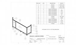
You can fill out cutlist properties for each body such as Desc., Mass, Revision, Material, etc.
(Expand the Cutlist folder in the FeatureTree, right-click on an item and click "Properties". )

Then make a BOM template with columns for the desired cutlist properties, not file properties. Save the template for multibody part usage only.

And yes, for moving parts you will need an assembly. You can use Move/Copy Body in a pinch, but it's not nearly as nice.

You just changed my life. I had been looking for this but hadn't grasped you have to right click on the cut list item, not the body itself. This was five minutes work to add a Description and Length property to each panel and then fill in the fields so now this cut list table is a mixture of automated population for the weldment and manual for the panels. Next step is to add columns and driven dimensions to auto populate the length and widths of the panels. Thanks so much!!

Zeumn Test.jpg
 
We haven't talked about design tables yet, which is another useful tool, but in the right application. If you don't know, it's way of using a spreadsheet to create and manage configurations of a part. As a bad example, When I started making these 8020 weldments I had one part file with all the panels for each frame in a design table, but it was very tedious to transfer measurements from each bespoke frame for six unique installations and to end up with 30 configurations of panel which don't have anything to do with each other except being the same source material. For these intimately dimensionally related parts, the multibody approach in one part file is much better. The canonical use for design tables is probably the way Solidworks itself handles screws, where you can configure a huge range sizes of a similar shape and then apply these parts in assemblies in many different applications.

As another example though, we've been doing versions of a lightweight face shield for docs who aren't happy with the one time use shields. The idea is it's more like a pair of sunglasses than a thing you tie onto your head. So we've been varying parameters like forehead radius and depth and length and inward curvature of the temples (the eyeglass industry term for the arms that go to your ears) to get different sizes, and there, the design table works really well. The key of course is to have a robust design that doesn't explode when you change parameters! The reason it's particularly good here is I can vary parameters systematically, like making a series of sizes each 5% smaller than the previous one, and see all the sizes in front of me at the same time.
 
Here's a few more favorites:

-Use Tab to hide components or bodies that are under your pointer (hovering, not clicking). To show, hover over the hidden part and press Shift+Tab. This works for both part files and assemblies.

-The S key is the "breadcrumbs" key. But it also activates the Search function so if you need a command that you can't find, press S and start typing. Suggestions will show up in the upper right-hand corner in the search box. When you find the command you want, you can hover over it and there will be an eye to the right of the description. Click on it and it will show an animation of how to find it from the toolbar.
 
Yes, that's what I mean. It can even ignite your computer. :D

I personally don't like 3D sketching because of the difficulty of defining entities and aligning to the desired axis. :cheers:

-I rather like the 3D sketch when doing structural designs for tubing/pipe/beams. It eliminates the need for creating an endless array of sketching planes with separate profiles/component models for each. It also allows you to define the mitered ends geometry, and can selectively create an appropriate joint for each end. Imagine 3 or more tubes (round, square, rectangular, etc.) sharing a common end joint. Some have to have a miter, some will have an overlap, some just abut the joint. Instead of determining each length, drawing each cut, and examining how they all interact you do this while designating the profile much faster. This will also allow a cut list to be generated with the correct dimensions, and allow a drawing for each one. Change to any of the component profiles is easy with no need to sketch another profile, just select a different profile from the list or a custom library. I think I may have also used 3D sketching for boundary surfacing and generating a path for driving an extrusion when defining a plane for sketching was too difficult/clumsy. It can, IIRC, hold constraints if you make a change within the parent/child relationship. Defining orientation is a bit clumsy until you get used to it because it starts with no references, that's what 3D sketching is. The order you assign references/dimensions can avoid sending the thing out in left field, use of the "back" button helps during reference. It's not great at everything but is my preference for jobs like creating frames that hold large containment vessels, piping, or any "path" that's going two directions at once from a reference. Much faster. Structural design work is likely what it was created for.

SolidWorks limitations: Not as good at surfacing as some other programs. Not as good at driving a changing profile along a path as others either.
 
We haven't talked about design tables yet, which is another useful tool, but in the right application. If you don't know, it's way of using a spreadsheet to create and manage configurations of a part. As a bad example, When I started making these 8020 weldments I had one part file with all the panels for each frame in a design table, but it was very tedious to transfer measurements from each bespoke frame for six unique installations and to end up with 30 configurations of panel which don't have anything to do with each other except being the same source material. For these intimately dimensionally related parts, the multibody approach in one part file is much better. The canonical use for design tables is probably the way Solidworks itself handles screws, where you can configure a huge range sizes of a similar shape and then apply these parts in assemblies in many different applications.

You know what weldment profiles are, right? You could make one for each 80/20 profile and apply it to sketch lines to automatically extrude.
 
You know what weldment profiles are, right? You could make one for each 80/20 profile and apply it to sketch lines to automatically extrude.

Sorry I wasn't very clear in my post. The 8020 is in a weldment but the panels, which fit in the 8020 slots with gaskets, were originally separate parts in a design table but are now part of the weldment part, and thanks to you have their own properties! In the example I showed I actually am using a simplified 8020 model since the 1010 series extrusion and the other original inch parts are such complex profiles (many extra little grooves) it causes graphics trouble. In fact we have the complete library of 8020 weldment profiles and you can have them too: They come from a guy named Amos Avery who posted them long ago at A Very Swell Idea, Inc. – Developing swell solutions for swell people… like you. See here for the original ones: 80/20 Weldment Profile Library Features – A Very Swell Idea, Inc. But since I'm learning new things all over this thread, just while writing this post I discovered Avery had also uploaded newer smooth 8020 profiles here: http://averyswellidea.com/swellideas/wp-content/uploads/2010/05/SmoothProfiles.zip

One thing about 8020 weldments is the automatic trim functionality when you're adding structural members doesn't work well and you have to use TrimExtend in End Trim mode and trim using the flat faces of the 8020 you're butting into. The auto trim wants the cut profile to follow the shape of the profile it's contacting, which of course doesn't work with 8020 as you end up with a slot shaped chunk sticking out of the end of your cut profile.
 
I hadn't considered the 80/20 profile varieties because I don't work with it on things I design. It is a product in widespread use for some applications, wonder what the graphics trouble is? Can't see it being from too much detail but I could be wrong. What happens when the mating surface is employed ("use surface") to trim or the "intersect" function? Grasping at straws here.
 
The original inch series of 80/20, the 1010, 1020, 2020 extrusions etc, have these extra grooves which are purportedly to help hold fasteners tight by providing more edges or something. All I know is it makes the bars harder to clean! The problem in CAD is that all that extra detail of the grooves makes it hard to see what you're doing. e.g. to trim you have to locate the flat face on the side of the slot. With the complex profile you can't tell what you're looking at unless you can see one end of the extrusion. It also annoys the shop staff because when you look at the drawings I make, the bars are all black from too many lines and they can't tell which bar is overlapping which at the joints. I specifically made the simplified profile in the example I posted earlier because my assembly guy complained about not being able to see the orientation of the butts.


1010 Detail.jpg
 
I haven't seen it mentioned yet, but a couple out-of-the-box shortcuts that I use all the time:

alt-f, then let go and press
s: save
a: save as
c: close
n: new (part, drawing, assy, etc.)

alt-w, then a number to go to another part window

Play around and find some, those are the ones I use all the time but anything that can be done all with the left hand is almost guaranteed to be a time saver.

I saw it mentioned earlier to use infinite length construction lines through the origin. Is there a way I'm unaware of to make it so that ALL new sketches come with infinite horizontal and vertical axes through the origin? Seems a waste of time to do it manually, and I almost always use them both in every sketch.
 
You can assign part numbers and descriptions to toolbox components. When you add one, click on "Add" under the part numbers box in the menu (as seen in the picture).
Then add your part number and description and it will autopopulate your BOM. If you have 2 sizes, you can select different descriptions in the box for each one.


http://[IMG]https://www.practicalma...nt.php?attachmentid=291742&d=1592242906[/IMG]
 

Attachments

  • 2020-06-15 13_33_02-Window.jpg
    2020-06-15 13_33_02-Window.jpg
    15 KB · Views: 31
I haven't seen it mentioned yet, but a couple out-of-the-box shortcuts that I use all the time:

alt-f, then let go and press
s: save
a: save as
c: close
n: new (part, drawing, assy, etc.)

alt-w, then a number to go to another part window

Play around and find some, those are the ones I use all the time but anything that can be done all with the left hand is almost guaranteed to be a time saver.

I saw it mentioned earlier to use infinite length construction lines through the origin. Is there a way I'm unaware of to make it so that ALL new sketches come with infinite horizontal and vertical axes through the origin? Seems a waste of time to do it manually, and I almost always use them both in every sketch.


I like the Alt+F shortcuts. However, I have hot-keys for most of that.
Ctrl+S for save (obviously), Ctrl+Spacebar for Open, Ctrl+Shift+Spacebar for Close, Alt+Z for Save-As.
Also, if you hold Ctrl+Tab it will show all the open documents and you can click on any of them.
 
We haven't talked about design tables yet, which is another useful tool, but in the right application. If you don't know, it's way of using a spreadsheet to create and manage configurations of a part. As a bad example, When I started making these 8020 weldments I had one part file with all the panels for each frame in a design table, but it was very tedious to transfer measurements from each bespoke frame for six unique installations and to end up with 30 configurations of panel which don't have anything to do with each other except being the same source material. For these intimately dimensionally related parts, the multibody approach in one part file is much better. The canonical use for design tables is probably the way Solidworks itself handles screws, where you can configure a huge range sizes of a similar shape and then apply these parts in assemblies in many different applications.

As another example though, we've been doing versions of a lightweight face shield for docs who aren't happy with the one time use shields. The idea is it's more like a pair of sunglasses than a thing you tie onto your head. So we've been varying parameters like forehead radius and depth and length and inward curvature of the temples (the eyeglass industry term for the arms that go to your ears) to get different sizes, and there, the design table works really well. The key of course is to have a robust design that doesn't explode when you change parameters! The reason it's particularly good here is I can vary parameters systematically, like making a series of sizes each 5% smaller than the previous one, and see all the sizes in front of me at the same time.


So a design table keeps all your dimensions and equations organized, right? And you can copy and paste values from cell to cell?
 
So a design table keeps all your dimensions and equations organized, right? And you can copy and paste values from cell to cell?

Much more than that. You can use all the equations you could in an excel sheet. For example, if you wanted to scale dimensions. Each row is a different configuration, and you can set whether features are suppressed or not across each configuration. You can even tie it to something like patterns, say you want to make wheels with different numbers of spokes.

One particular project I did was for a casting, which involves compensating for shrinkage and such when making the pattern. Different features shrink separately, and the design table was perfect. Take 2% here, 3% there.


Nice, I'll have to check that out.
 
Any of you wise guys out there know how to draw a free-form line through space?

Think a cord or hose. I've tried splines and arcs but they want to align to a primary plane or axis.

It's got me stumped.
 
Any of you wise guys out there know how to draw a free-form line through space?

Think a cord or hose. I've tried splines and arcs but they want to align to a primary plane or axis.

It's got me stumped.

projected curve

from 2 different sketches on 2 different planes

go to help and read about is or youtube for vids YouTube

projected curve.jpg


Back
Top