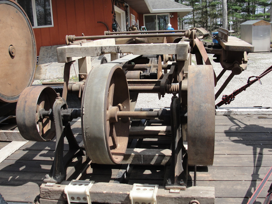
In my opinion, 800 rpm is fast for the type of lineshaft and type/diameter pulleys on it. Those are cast iron pulleys with what appears to be about 12" or more in diameter. The type lineshaft bearings were designed for lineshaft turning more on the order of 200-300 rpm. The bearings are being used to support a short piece of lineshaft, which is more of a 'jackshaft' or 'countershaft'. A lot of factors play into how this sort of thing will run. Namely: how good a fit and how concentric (how much runout) do the pulleys have on the shaft ? I'd at least use a fixed pointer (like a surface gauge) to see how badly the pulleys are running out on the rim and face. Running pulleys like the ones in the picture up at 800 rpm would require the pulleys to be running quite true to the shaft in both rim and face runout.
The other issue is the condition of the shaft. The type of lineshaft bearing supports in the picture are made for aligning line shafting when the bearing supports are mounted to a building or structure that might not be all that accurately built. These are not what could be termed 'rigid' bearing supports. Lineshafting, in service, will often tend to 'bow' slightly (deflect) due to a combination of belt-pulls, weight of the pulleys, and the shaft and pulleys wanting to move to a 'dynamic center' when the shaft is turning. The type bearing supports in this post address this, as well as alignment in a building which may do some moving on its own (settling of the building over time, increased floor loads on the floor above the lineshafting, wood framing moving with humidity). Line shafting, as 'commercially available' was never the straightest thing. It was OK for slow speed/long span applications as things were loose enough for it to run properly.
For wahtever reason, line shafting seems to have been made to odd 1/16th sizes, with 1 7/16" diameter being quite popular. I'd take the chunk of shafting to be used in this project and set it up in a 4 jaw lathe chuck. Indicate each end and put a center in it. Set it up between centers on the lathe and roll it over by hand and use a dial indicator to see how straight the shaft is. Running these types/sizes of pulleys at 800 rpm will require the shaft to be straight, aside from the pulleys running dead true on it.
As for the bearings, they were once cast iron bearings. Due to neglect or maybe running too tight belts and little or no lube, and maybe a lot faster than things should have run, the bearing bores are worn way far out of round. Two thoughts here: bore the bearings a bit oversize and babbitt them. They will need to be in good alignment and set up with a good close clearance and proper oil grooving to run a shaft with those pulleys at 800 rpm. Line shaft bearings made for more typical line shaft speeds (200-300 rpm) would not necessarily hold up in service at 800 rpm. This may be why the bearings in the photos are so 'wallowed out'.
I'd also suggest doing a static balance on the assembled shaft and pulleys. It is quite common to see balance weights riveted to the inside of the rims of larger line shaft pulleys made to run at higher speeds or being large enough diameter to have a high rim speed.
The 'magic number' for sawmill saws, buzz saws, and circular saws is 10,000 feet per minute for the rim speed (speed at the tips of the saw's teeth). For a circular saw to cut properly, 10,000 fpm is the number to shoot for to get good cutting. If the diameter of the saw is known, and the governed rpm of the engine is known, some simple math will determine if the pulleys on the jackshaft, saw arbor, and engine shaft are properly sized. I've been around lineshafting enough to know it is an 'interesting proposition'. The old shafting may be bowed or simply too worn at the journal areas to be used. A piece of turned-ground-polished stock would make a good high speed jackshaft if the old shafting is not usable. I've seen some real horror shows when people used cold rolled shafting on higher speed machinery and milled keyways into it. Cold rolled steel likes to 'self relieve' or you release 'locked in stresses' when you machine it assymetrically. Milling a few heavy keyways in CRS shafting all on the same side of the shaft really caused the shaft to warp and set up some hellacious vibration and knock the stuffings out of some ball bearing pillow blocks. In old mills and shops with long line shafts, the shafting is 'live' in use. Heavy wire rings are often placed around the shafting to keep dirt from accumulating on the shafting. In service as the load on the shafting changes, those rings literally dance up and back along the shafting, limited only by pulley hubs or bearings. As load changes, the distance and frequency the rings move on the shafting changes with it. Lots to consider when making a lineshaft, even a short one, intended to run at higher speeds.