just Dave
Cast Iron
- Joined
- Jan 18, 2023
- Location
- Kansas City
.001 is the goal. Old men can still hit that.Yes! Set the indicator so you get nearly a full swing and land at 12:00. With some practice you'll be able to land within .010" or so.
Follow along with the video below to see how to install our site as a web app on your home screen.
Note: This feature may not be available in some browsers.
.001 is the goal. Old men can still hit that.Yes! Set the indicator so you get nearly a full swing and land at 12:00. With some practice you'll be able to land within .010" or so.
I never got that good, maybe within 0.005". This is one of those times where an extra large dial face is a big help..001 is the goal. Old men can still hit that.
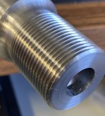
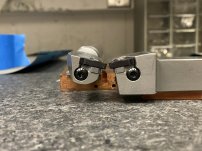
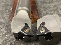
I did try threading with a normal holder up to a large relived area and it does look better than the boring bar. I did that one at 90deg in just to test how it went. I’m going to try it again at 30deg. Im including pictures of both holders side by side. They are both 16tpi full profile Stainless geometry inserts. I’m using a monarch/weiler 517 lathe. I tried it on a emco maximat v13 that I much prefer but I believe the thread half nut is too loose or something is broken in the head because it won’t pick up on the same thread location.Yes! Set the indicator so you get nearly a full swing and land at 12:00. With some practice you'll be able to land within .010" or so.


If you have a sloppy half nut then don't disengage it. Stop the spindle then reverse to pick back up at the stary of the thread. Low rpm in these situations ir friend, slows things down.I did try threading with a normal holder up to a large relived area and it does look better than the boring bar. I did that one at 90deg in just to test how it went. I’m going to try it again at 30deg. Im including pictures of both holders side by side. They are both 16tpi full profile Stainless geometry inserts. I’m using a monarch/weiler 517 lathe. I tried it on a emco maximat v13 that I much prefer but I believe the thread half nut is too loose or something is broken in the head because it won’t pick up on the same thread location.
View attachment 397617View attachment 397618View attachment 397619
I'm not a fan of the 30deg approach. I find it easier to plunge directly and it doesn't change your Z position.I did try threading with a normal holder up to a large relived area and it does look better than the boring bar. I did that one at 90deg in just to test how it went. I’m going to try it again at 30deg. Im including pictures of both holders side by side. They are both 16tpi full profile Stainless geometry inserts. I’m using a monarch/weiler 517 lathe. I tried it on a emco maximat v13 that I much prefer but I believe the thread half nut is too loose or something is broken in the head because it won’t pick up on the same thread location.
View attachment 397617View attachment 397618View attachment 397619
Now we can see the boring bar does have a shim seat. What is the angle marked on the insert?I did try threading with a normal holder up to a large relived area and it does look better than the boring bar. I did that one at 90deg in just to test how it went. I’m going to try it again at 30deg. Im including pictures of both holders side by side. They are both 16tpi full profile Stainless geometry inserts. I’m using a monarch/weiler 517 lathe. I tried it on a emco maximat v13 that I much prefer but I believe the thread half nut is too loose or something is broken in the head because it won’t pick up on the same thread location.
View attachment 397617View attachment 397618View attachment 397619
Get two pieces of high speed xteel and a white wheel on the bench grinder and a fishtail gage. Grind a radius relief into the first one, plunge that baby into the workpiece to a little under thread depth at the headstock end of the thread. That makes a stronger thread than what you are doing.
Now we can see the boring bar does have a shim seat. What is the angle marked on the insert?
I don't think you mention the major diameter so I'm guessing 3/4. The helix angle for 3/4-16 is about 1.5* so you can use a 1* or 2* shim. Some bars already have an angle built in to the pocket so that must be taken into account. Understand that there is a range of helix angles each insert/shim/bar setup can effectively cut. What good for one may or may not work on another. You've got to do some figuring.
If your'e not using a -1* or -2* shim the insert is tilted the wrong way and will likely rub on the flanks, resulting in poor threads and broken inserts. Softer materials will be more forgiving but still not good.
I'm not a fan of the 30deg approach. I find it easier to plunge directly and it doesn't change your Z position.
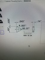
The inserts I am using have a .007” radius at the point. For the external bar I’m using an Iscar 16ER16UN IC908. The insert on the boring bar is a carmex 16EL16UN BMA (external 16EL insert on a holder meant for a 16IR)Now we can see the boring bar does have a shim seat. What is the angle marked on the insert?
I don't think you mention the major diameter so I'm guessing 3/4. The helix angle for 3/4-16 is about 1.5* so you can use a 1* or 2* shim. Some bars already have an angle built in to the pocket so that must be taken into account. Understand that there is a range of helix angles each insert/shim/bar setup can effectively cut. What good for one may or may not work on another. You've got to do some figuring.
If your'e not using a -1* or -2* shim the insert is tilted the wrong way and will likely rub on the flanks, resulting in poor threads and broken inserts. Softer materials will be more forgiving but still not good.
About the radius thread relief this is 100% correct. Maybe you are just practicing threading to a shoulder but you must understand you are cutting a very poor defacto thread relief anyway. The worst you can make as far as a stress riser. A wider thread relief, even flat bottom, is a better solution and easier in every way.
Even with a CNC lathe running a canned cycle you'll have this crappy relief. A ramp in can be programmed longhand and is much preferred.
Please tell use why you are so opposed to a thread relief! Maybe you have a very good reason. We'd like to hear it!


I may have used that trick to get metric threads on an inch-only machine. Just once, in a pinch.Another 'cheat' you can do is thread 'pretty close' to the final depth, then run a die down the threads to finish them. I don't like to do this as I believe you can get a better thread by single pointing them...but in some cases it makes a project fly. It's also a good way to thread all the way to a shoulder. We used to sometimes grind a die on the surface grinder so its threads had no lead-in at all and you would effectively run the thread on the part into the shoulder. But....I have to wonder why you need threads that close to the shoulder....
I'm using about 325 rpm with a little oil. Depth of cut something like .005 each pass until end cuts which may be .002 - .001.I’m turning the lathe as slow as it will go at 46rpm.
dead right here. Carbide inserts and hss operate in different metal deformation zones of the parent material. Either of them working in the wrong zone will give you a bad finish. In order of increasing surface speed:46rpm is so slow you'll never get a good finish.
Cut a proper thread relief, get the RPMs up around 200-250 and practice it. You'll be surprised how much better the threads will look.
Notice
This website or its third-party tools process personal data (e.g. browsing data or IP addresses) and use cookies or other identifiers, which are necessary for its functioning and required to achieve the purposes illustrated in the cookie policy. To learn more, please refer to the cookie policy. In case of sale of your personal information, you may opt out by sending us an email via our Contact Us page. To find out more about the categories of personal information collected and the purposes for which such information will be used, please refer to our privacy policy. You accept the use of cookies or other identifiers by closing or dismissing this notice, by scrolling this page, by clicking a link or button or by continuing to browse otherwise.
