What's new
What's new

Toolmaster 1D Generic machinist question.

rgsheehan

Plastic
Joined
Jun 18, 2020
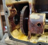
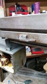
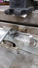
I have finally gotten around to re-installing the cross axis power feed on my Toolmaster. Removed the cover, removed some varnish on the 'C'? (lower, front one) shaft that was restricting the gear pack from sliding back and forth, and cleaned it out as best I could. All the gears and shafts -looked- okay (no chipped teeth, no slop) so I reinstalled the box back onto the table with the motor and front cover removed (Motor runs fine, tested separately). I made a test driveshaft so I could operate the gearbox with a cordless drillmotor. That worked fine on the bench, all the shafts/gears appeared to work well, the output gear (the wide brass one) spinning happily. But..., once installed, with the load of the table, the output shaft stopped moving, even with the input being driven. The larger (but thin) gear shown in the pictures is turning, but the shaft it is supposedly keyed to is not. So the key is sheared or not there, right? In trying to figure out how to remove that, my machinist eagle eyes (yeah right) spot an access port of the side of the case! Complete with a hex head socket. What could be easier? I just unscrew that plug, remove a couple of snap rings, slide the shaft out, replace the key, and put it all together!
Yeah, not so much.
Turns out (pun) that hex is part of a -smaller- plug threaded into the big one. So, it came out and the big one did not, and has not. I don't know if it is threaded in there and I need a special tool, or 'just' pressed in, or what.
My questions involve:
1. Is it even reasonable (is there room) that that shaft can come out, I can replace the key, and get it back together, or am I doomed to having to remove the big worm gear driven part.
2. What is the sense of having that hex plug in the middle of the bigger plug?
3. In general how are any of the plugs 'supposed' to be removed.

The manual is of course silent on all this. And frankly, other than the drawings, I find the manual of little use.
I have never used any other mill, so I have no comparison experience, but I really like this machine. I think it is good at dealing with all my newbe mistakes, luckily none of which has broken anything.

Anyway, if anybody has any input on how to get out of this kind of a ditch, I would very much appreciate it.


rgsheehan
 

Attachments

  • CTM_GB1.jpg
    CTM_GB1.jpg
    358.4 KB · Views: 13
  • CTM_GB2.jpg
    CTM_GB2.jpg
    555.4 KB · Views: 13
The X-axis gearbox on my Toolmaster 1-B had the same problem. The Woodruff (or was it a Hi-Pro?) key that connects that large gear to the shaft is a weak spot, and it sheared, damaging the keyway and bore of the gear, and the pocket in the shaft.

Not sure which manual you have, but the Toolmaster manuals I have reference the removal and disassembly of the X-axis powerfeed gearbox (pp. 18 and 19 of M-1890-1, for example). Are you referring to the Operator's Instruction Book M-1941?

First, those "plugs" on the side of the case were not threaded from the factory. Someone has been into the box before, and threaded it instead of repeating the factory's press-fit plug. On the access plug that you mentioned, it's a one-piece disc, and is just a press fit into the cast housing opening. You can pull it using the threads that someone tapped into it. The factory method is to drive the entire disc into the housing, and then retrieve it from the front since the cover is off.

Some of the other plugs appear to be two pieces, a small plug in the center of a larger disc. These are actually a small plug in the middle of a bronze bushing that holds the end of one of the cross shafts. The small plug (a) seals in the lubricant, and (b) provides a method to extract the shaft and bushing. The factory method for removing the two-piece plugs is to drill and tap the small plug for a 1/4-20 thread, then pull the small plug with a 1/4-20 bolt or similar. You have to be careful not to drill past the small plug and into the end of the shaft if it's a two-piece plug! The drill and tap the bronze bearing to pull it.

100_0499.jpeg 100_0503.jpeg 100_0504.jpeg

The factory method for removing that large thin gear on the left end of the A shaft is to remove the disc on the left side of the housing, remove the split rings (one on the left side of the gear, the other on the right side of the bearing to the right of the gear), drive the shaft through the large gear to the left just far enough to remove the Woodruff key, then drive the shaft to the right and out of the housing, which will free the gear.

The good news is that you don't have to remove the big worm gear, or any of the other shafts.

The problem is that the key has sheared and/or the pocket in the shaft has been deformed. Simply disassembling and replacing the key won't solve the problem, at least not for very long.
 
Last edited:
So here's how I fixed mine.

The trick was to fix the interface between the large thin gear and the shaft so that it wouldn't (hopefully) fail again, and could still be assembled and disassembled. I ruled out a Woodruff key, and decided to go with a roll pin.

First, I cleaned up the end of the shaft, which had been damaged by the Woodruff key failure. I probably had to turn down the diameter a bit, but only where the gear is on the shaft; any farther to the right, and I would have been into the part of the gear that turns in the bronze bearing.

I bored out the hole in the large thin gear, enough to clean up the damaged keyway. I don't recall now exactly how large the new bore was, but I think I bored enough to completely remove the keyway.

Than I made a shouldered bushing, with the bushing OD a press fit into the new larger hole in the gear, and long enough to completely extend from the flat left side of the gear through the shoulder on the right side of the gear. The ID of the bushing is a light press fit (push fit) onto the shaft, as this interface has to be put together with the shaft already in the gearbox housing. The bushing also has a shoulder, fit tight up against the left face of the gear, and the same OD as the shoulder on the right side of the gear. Like this:

100_1017.jpeg 100_1018.jpeg 100_1019.jpeg 100_1020.jpeg 100_1021.jpeg

It's hard to see from the right side of the gear, but you can just make out the separation line between the ID of the shoulder on the gear blank, and the bushing.

In these photos, the assembly is set up to drill though the gear shoulder, the bushing, and the shaft for a small diameter roll pin. I don't remember now what size, maybe 3/32"? After drilling, the gear (with the bushing, which is now permanent in the gear) and the shaft will be separated and then installed in the gearbox housing per the factory. No more Woodruff key, and no more split ring on the left side of the gear; you'll still need to reinstall the split ring on the right side to control axial movement of the shaft.

I then cleaned up the rest of the gearbox, replaced all of the bronze bearings and plugs, painted it inside and out, and put it back together.

100_1022.jpeg 100_1023.jpeg 100_1024.jpeg 100_1025.jpeg 100_1026.jpeg

I did this repair on my Toolmaster several years ago, and have had no problems with the gearbox since then. I've not tested the roll pin to failure, but I don't try to take hogging cuts on this machine with the gearbox engaged. The pin is probably not as strong as the Woodruff key when new, but obviously the key design has a weak point as well.
 
Last edited:
Wow. That is a seriously awesome answer. From it, I went and made a little puller and the bigger plug popped right out. You are exactly right about someone else having been into this gearbox, the threaded hole in the bigger plug holding the little hex plug is not even drilled on center. But it worked well enough to pull it out. I'll work on getting the plug on the the other side out tomorrow. Not sure I have the machinist chops to pull off a long term fix to the gear and shaft the way you did, but we'll see what things look like when I get the shaft removed. I might have to hire that one out.

Really, I can't thank you enough.

rgsheehan

P.S. Even though I don't do heavy duty work with this machine, I am wondering if it would make sense to put some kind of clutch or shear-able adapter on the motor input shaft so the machine wouldn't get broken again, either by it's own or from some mistake of mine.
From what I can see, if something like that happened, it would be a lot easier to pull the motor, replace a broken coupling and reassemble, rather than have to disassemble the box, or, heaven help me, try to source one of those gears.
 
The repair wasn't particularly difficult once I had an idea of how I wanted to revise the original factory design. Easiest to do most of the work on a lathe, but the entire project could be done on the Toolmaster, just not as quickly or conveniently. There's only one way to get the "chops" - jump in and try it. If you have questions along the way, I'm happy to help.

Finding a replacement gear will be very difficult. But if you have a dividing head and the right gear cutter, your Toolmaster can make it's own replacement gear if needed.

I thought about trying some sort of shear coupling on the motor drive, but decided to fix the Woodruff key with a roll pin, and try that solution first. So far, so good. At least on my Toolmaster, I think the failure inside the gearbox was due to the box running out of travel to the right, and hitting the lever for the saddle lock. On my machine, the lock lever was missing entirely, all I had was the stub of the threaded shaft to tighten the lock. If the operator isn't paying attention when in powerfeed to the right, the gearbox will hit the lever before the auto trip disengages the feed - a design flaw no doubt. I'm guessing that when that happened on my Toolmaster, the Woodruff key in the gear was the weakest link. The moveable trips are missing from my mill, but I really should make at least the left one to prevent this from happening again.
 
Make sure the permanent auto disengages for the power feed are present. If they are there, I don’t think there is much to worry about in the feed box. I have a 1-D with X power feed and it works fine. Leaks oil, but that is it. Seems quill power feed is more prone to failures.
 
My mill still has the kickouts. The sheared woodruff key came out easily and had not damaged the gear or the shaft very much. A little deburring and they look good enough to me. Both the replacement woodruff key and the key for the sliding triple gear did not look like they were the right 'height'. They barely rose up proud of the shaft by much, maybe rising up into the slot on the gears by 1/4 of the height of the slot at most. That just did not seem right to me so I ordered some larger keystock (.125 x .1875) from McMaster Carr and made some new keys. After some hand fitting, the shaft and gears are back in place, and the drive is moving the table while being driven by my cordless drill / adapter shaft test setup. I had to make a new bushing for the motor shaft since the original nylon one was all dried and cracking. Made the new one out of delrin, and got some boring and turning practice on the South Bend 9C to boot. I messed up and reinstalled the left handwheel before installing the new seal on that end of the leadscrew, so that has to come back off. After that, make a new front cover gasket, check the 'timing' on the left/right engagement cam, reinstall the motor, fill 'er up with oil, and off we go.

Yeah, the quill power feed is also a problem. Dumps oil out as fast as I can put it in. Seems like a lot of backlash in the handwheel. The mill is pretty darn loud at the higher speeds (1400+ rpm) when it is in gear (not in 'neutral'). It is pretty quiet with the motor running with the transmission in neutral. I'm hoping some of that noise is in the power down feed and not the spindle bearings. Won't find out though, until I get some time to play with the new power feed!

Thanks again for the help.
 

Attachments

  • 20230329_143636.jpg
    20230329_143636.jpg
    324.6 KB · Views: 1
  • 20230329_143621.jpg
    20230329_143621.jpg
    466.4 KB · Views: 1
My mill head is rather noisy as well. Someday I need to tear it all apart and fix what needs fixing. Steve Watkins (Steve Watkins at work) has a number of good videos on youtube of repair work he did on a Toolmaster 1-D.
 
Glad to hear that you made headway with the X-axis power feed.

Lots of little parts in that power feed assembly. I recall having to remove the gearbox more than once, too. :)

My Toolmaster is a 1-B, so I'm not familiar with the workings of the 1-D head, sorry.
 
Make sure the permanent auto disengages for the power feed are present. If they are there, I don’t think there is much to worry about in the feed box. I have a 1-D with X power feed and it works fine. Leaks oil, but that is it. Seems quill power feed is more prone to failures.
Hello Gearclash,
Thanks again for your input on my X powerfeed project. It seems to be working fine so far.

Since you have a 1-D, I was curious if you know if the spindle drawbar can be removed by simply removing the plate up high that covers the lock knob, the one you shove in to lock the spindle to change tools, and pulling the drawbar out the top? The reason I ask is I bought a boring head on Ebay. It is made in Taiwan and appears to be pretty darn well made, especially for the money. However, the folks selling it, based in California but clearly not English speakers listed the tool as
<<NEW NMTB 40 4INCH BORING HEAD WITH 8PCS 18MM CARBIDE INSERTS 2084 >> . The listing is full of a mishmash of metric and imperial specs. It is not a 4 inch head, it is 83 mm (~3.26") or so. The carbide holder shanks are not 18mm, they are 20mm. The graduations on the adjustment are listed as 0.001", but the actual dial shows 0.01mm. I can live with all that, but the taper adapter appears to be 40 taper, but it has a metric 16mm diameter with a 2mm thread, so not really NMTB 40, right? Anyway, that's not gonna work. I contacted the seller who responded saying a 5/8-11 adapter is not available. They did offer to take it back and refund my money, but it is the last one they have of this kind, nobody else seems to have this Taiwan made version at anywhere near the price, and I don't really want to pay the freight to ship it back. So I am left with trying to modify the adapter I have (bore out the metric threads and make a threaded sleeve, or some such), or, if it's not too much of a pain to swap one in and out, just make a new drawbar with the metric thread on the end.

Sorry for the long winded explanation, but if you know anything about removing the drawbar, I would be very interested.
Thanks,
Russ Sheehan
 
@rgsheehan I can’t help you with 1-D drawbar removal; however I’m sure Steve Watkins had the drawbar out of the 1-D that he fixed up. I would think he has the removal of it covered in one of his videos on that project. He is under “Steve Watkins at work” on youtube. NMTB40 differs from other 40 tapers only in that the internal threads for the drawbar are in an extension beyond the taper itself. The tapers have the same specs. I learned that the drawbar in my 1-D is long enough to adequately catch *some* CAT 40 tool holders, in addition to NMTB40 tool holders. That doesn’t solve your metric thread problem though.

My recommendation would be to either make the boring head work with the existing draw bar or send it back. It is quite easy to change tool holders on a 1-D as it is (no reaching on top of the head to hold the spindle) so it would be really awkward to have to switch drawbars to switch tool holders.
 
Ok, thanks for the input. I have watched all of the Watkins (and Don) videos I can find where they are working on the Toolmaster. Don't recall any of them showing drawbar removal or installation, but maybe I'll skim them again. I try not to get crazy when tightening the drawbar anyway since I don't think that is necessary given the size of the taper (alignment) and the drive dogs (no rotational slipping), so the sleeve (press fit and loctite) might work out. We'll see.
Thanks again.
 
@rgsheehan
This video may contain the removal of the draw bar but I’m not sure. If nothing else it will get you into the Toolmaster rebuild videos.


Back
Top