What's new
What's new

Using V-point Threading Inserts on CNC Turning Center

Yeah. Pretty sure the Machinery's Handbook gives the MAX diameter for the root of an O.D. thread.

OP, I'm another that doesn't understand your problem. The pitch diameter determines fit. You have a pitch mic. The only time the insert radius has an affect on fit is when it gets too large. The no-go gauge will go while the go-gauge won't when that happens. You don't even have to look at the insert to know it is time for a new corner. If you only have a pitch mic and wires, then I can see you getting into trouble at some point.

Once I get the thread where I want it, I use an optical comparator to measure root diameter, and change my X-value to that and the P-thread height in the program to reflect the actual thread height. (I'm using canned threading cycles. Mostly G76 cuz we mostly have Fanuc controls.) Sometimes you have to lie, but that is for another post.
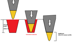
I made this diagram that should clear some things up. As you can see, the proper profile is not obtained until the V-point threading insert is fed in an extra bit.
threading issue diagram.png
I think you mean to say, "the minor diameter comes to a sharp point because we are using V inserts, and this means that the pitch diameter is not correct."

As stated above, you do need to cut deeper, by a factor of 1.4. In other words, if the formulas tell you to cut 1mm deep with a correctly-flatted tool, you would need to cut 1.4mm deep with the sharp tool.
Yes this is a better way to describe it. So this ratio is universal? In other words when we use these tools we need to increase the thread depth by a factor of 1.4? I think we added 7 or 8 thou on this one, I am curious to see how close that is to the output of the formula.
 

Attachments

  • threading issue diagram.png
    threading issue diagram.png
    45.1 KB · Views: 4
I made this diagram that should clear some things up. As you can see, the proper profile is not obtained until the V-point threading insert is fed in an extra bit.
View attachment 379520

Yes this is a better way to describe it. So this ratio is universal? In other words when we use these tools we need to increase the thread depth by a factor of 1.4? I think we added 7 or 8 thou on this one, I am curious to see how close that is to the output of the formula.
The 1.4 figure should work for any 60-degree UN or Metric profile, for external threads, when using a sharply-pointed insert
 
I made this diagram that should clear some things up. As you can see, the proper profile is not obtained until the V-point threading insert is fed in an extra bit.
View attachment 379520

Yes this is a better way to describe it. So this ratio is universal? In other words when we use these tools we need to increase the thread depth by a factor of 1.4? I think we added 7 or 8 thou on this one, I am curious to see how close that is to the output of the formula.
The explanation is so simple but I did not know this. Thank you for explaining with a nice figure.
 
I have analysed the 1.4 figure:
1. It is based on basic profile of a metric thread, for which the depth of thread is 0.54127 x Pitch
2. It also assumes that the insert tip has zero radius.

The depth of thread in threading charts is based on design profile of metric threads, which includes the fillet depth also, which makes depth of thread = 0.61344 x Pitch. This is the depth which is used for machining.
Moreover, the insert tip will have some radius.
Therefore, the 1.4 figure is only approximate, but it can be a good starting point.

In case of internal threads, modified depth = 1.2 x original depth
 
Last edited:
Lovely picture of what happens with a sharp tool. Hope you don't mind me stealing it to show the next guy I have to explain things to!

If you set the tool up on a manual machine and use the Zero-to-Zero threading method its easy to measure the actual extra infeed needed to get a correct profile as measured using thread wires.

With the Zero-to-Zero method you start by touching the tool to the work and zeroing both top and compound slide dials. Then you move the tool clear of the end of the work, feed the cross slide forwards from zero by the "book" thread depth and reset the dial to zero.

Pull back the compound slide enough for first cut clearance. Use the compound slide to apply cuts. Make the cuts with the cross slide on zero, pull it back for clearance on the return path.

When both dials read zero and all spring has been worked out you have cut what you set. With anything other than a full profile insert that will be too shallow.

Make further cuts applying extra feed with the cross slide until the measured size is right. The cross slide dial now reads the extra cut needed. DRO on the cross makes it less tedious and more accurate.

Try not to drop the thread wires in the chip tray! i've lost a couple that way.

Clive
 
It seems the many /most thread-turning insert for various threads are simply the angel (perhaps 60 or 55*) and a nose radius or flat. I think a good way to understand is the draw the insert, consider the point flat or radius.. and figure out the infeed.
1 divided by TPI is the 30* infeed for a sharp point insert/bit...so start with that.
Likely after figuring out a couple of threads, you will be able to nail the infeed within a couple of thousandths in your head.
I have made my own chart of in-feed for @straight and 30* but it is with the proper nose flat/radius. so using an insert I would have to figure in what nose the insert has.
A thread-turning insert for a specific thread may avoid any problem because the distance from the major to the root dia may be built in the insert.

Thread spicific: https://www.ingersoll-imc.com/product-family/377903
 
Last edited:
Too pointy threading insert will sometime make the coarse thread right. Due to the thread spec, there is minimum width to maintain the minor diameter not dropping below minimum to get the right pitch diameter. The solution is to grind the pointy tip a little. Example with 4.125 - 3 TPI - 2A External Threads. Root Width is 0.083"
 

Attachments

  • 123.png
    123.png
    212.3 KB · Views: 1


Back
Top