What's new
What's new

Valve Adjust Shim Material?

TGTool

Titanium
Joined
Sep 22, 2006
Location
Stillwater, Oklahoma
Anyone with actual experience in this realm may be a long shot but I'm sure there will be opinions too.

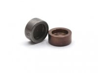
I need some adjustment shims for a 1980's Maserati 6 cyl which are the little caps on the valve stem similar to Alfa but not identical so plan to make some.

Machining itself isn't a particular challenge but I'm wondering about material. I had one tested at my heat treater and it came out barely 50 Rc, which surprised me at first. Then I recalled hearing that one Maserati race failure was from cracked valve shims so I see their point. I'd planned on using O-1 as readily available in 10mm stock and drawing them back to 50 Rc or thereabouts.

Recently it occurred to me to wonder if S7 had any advantage. In service the shims see compression but it's over the end of the valve stem and the cam follower so not a concentrated hit as in chisels, for example. All told it just "feels" to me that O-1 drawn back to only moderately hard ought to be plenty good enough but I'll solicit experience or alternate opinions.
Have these become unavailable? I sold my entire assortment of these shims to a guy in Minnesota a year ago. Probably had 200 of them. I can't imagine making them if they're available.
 
Never made any myself but I've known others who used O-1 and were fine as long as not left too hard after heat treating.

Main thing is to make sure the finish is smooth so no stress raisers to start cracks. Also, if you are using a torch instead of an oven, wrap soft iron wire around the OD as a handle as far away from the cap end as possible. Doesn't matter if that part is a little soft but the shim part is important.
 
Thanks, nice to have some knowledgeable answers. Shims are small cups 10mm OD, 7mm ID, and 7-8mm tall so 10mm drill rod makes a good starting point.

Yeah, they're available but something like $7 apiece so making up a set for occasional adjustments is something of a hurdle. Having a range of a few that can be ground to size seemed like an easier approach. And we're machinists, after all, so often not limited by absence of spare parts.

Brian, it sounds like you've been there. You'll probably appreciate that the guy I got this from said, "When you show up at the Maserati Club events and tell them you have a Bi-Turbo they'll say, 'I'm so sorry.'"
 
Sounds like the cup top wears on the cam lobe while the shim stack wears on the valve stem. Really just the bottom most shim will wear. If I am understanding the geometry I do not think the diameter is critical. You could get shim disks from any source and grind the outer diameter down to fit inside the hat. As long as there is some clearance all around they should work fine shouldn't they?
This method uses a factory hardened special steel as long as your grinding does not draw the temper. Seems better andf easier then making a guess at material and heat treat.
Bill D
Edit: so a stack of coins 7mm in diameter?
 
Without seeing the layout it's hard to tell what the shim is actually doing....is it a spacer only or does it take wiping forces such as from a cam lobe? If it is just taking up space, what you are describing is known as a lash cap, to the hot rod world. They take some motion from the rocker arms but it's not much, if the engine is set up properly. What touches the Maserati shim on either side? The valve tip on one side, and on the other?
 
At least it is not an Aston Martin, no shims at all, IDK about the new ones but on the old ones you changed the whole bucket as they came in different thickness so you could set the valves. When doing a valve job you just grind the stems.
 
Without seeing the layout it's hard to tell what the shim is actually doing....is it a spacer only or does it take wiping forces such as from a cam lobe? If it is just taking up space, what you are describing is known as a lash cap, to the hot rod world. They take some motion from the rocker arms but it's not much, if the engine is set up properly. What touches the Maserati shim on either side? The valve tip on one side, and on the other?
The inside of the bucket. 650 4 cyl. Kawasaki motorcycles were like that in the late 70's
 
In the 1980's I probably did more BiTurbo engines than almost anyone in America. They had their share of pitfalls. More people design a door handle on a GM car than probably designed the entire BiTurbo. They COULD be made somewhat bulletproof, as I rebuilt an engine at 25,000 miles that made it to 220,000 miles before it grenaded. I did so many of these cars when the local dealer gave up on the cars, I was able to buy parts direct from Maserati North America.

Beware of the intake valve shims, While TWO valves are being pushed down by one cup, it's HIGHLY important to have the height of the two shims exact. Otherwise it puts a side load on your cup that pushes down on them and wears out the cambox. I used an expandable valve guide pilot and did slight corrections in height using my valve grinder. The engine has numerous pitfalls that caused them to leak or bend valves at very low mileage,. BUT using the correct adhesives on the cambox gaskets, could make them last a LONG time. With full engine oil pressure going down the middle of these 3/8ths inch wide paper gasket was a recipe for failure. BEWARE that the THICKNESS of the cambox gasket varied, which can totally screw up all of your clearances.

I still have a LOT of factory tools for doing the gearboxes and differentials. Unfortunately I NEEDED those tools way too often. I saw a pretty clean looking BiTurbo sell on BAT for around 25K. I feel sorry for that buyer unless he knows someone who has worked on these cars.
 
Go to a Ducati bike dealer and take a look at Testastretta valve opener shims. 998 model for reference The stem tip measures 6.78mm IIRC the height range runs from 2 to 3.2mm. *I'm too lazy to climb up in my garage attic to dig my assortment out and measure them.

shims.jpg
 
Brian,

Thanks for sharing your experience. What kind of gasket dressing did you think worked best? My mentor, god rest him, swore by Hylomar HPF but I don't know when that became available.

The collective experience was that the left cam box particularly could run dry but that was usually attributed to the sintered oil filter in the line that they later recommended be removed. I don't remember hearing mention of leakage past the gasket covering the oil gallery being a culprit, but that's another oil loss location. I thought it was also at a disadvantage being fed from the rear main bearing after all the mains and rods had gotten their allotement

For others who haven't seen specifics of this engine design, they used two intake and one exhaust valve. To actuate the two intakes, they used the widened rim of the cam follower cup and the adjustment shims simply rode on the rim. Clever Italian arrangement (sort of) and maybe one that would never have occurred to British engine designers.

 BiTurbo Int-Ex.png
 
Brian,

Thanks for sharing your experience. What kind of gasket dressing did you think worked best? My mentor, god rest him, swore by Hylomar HPF but I don't know when that became available.

The collective experience was that the left cam box particularly could run dry but that was usually attributed to the sintered oil filter in the line that they later recommended be removed. I don't remember hearing mention of leakage past the gasket covering the oil gallery being a culprit, but that's another oil loss location. I thought it was also at a disadvantage being fed from the rear main bearing after all the mains and rods had gotten their allotement

For others who haven't seen specifics of this engine design, they used two intake and one exhaust valve. To actuate the two intakes, they used the widened rim of the cam follower cup and the adjustment shims simply rode on the rim. Clever Italian arrangement (sort of) and maybe one that would never have occurred to British engine designers.

View attachment 368102
 
Clever design...? More like a design by someone who wouldn't be around by the time it reached the proving grounds, much less by the time it saw a few years of service.
Nothing clever about that shit show. Pretty clear why it is critical that you have exactly the same clearance on each valve.

I'm sure it's a source of deep pain and perpetual regret at the Maserati factory that they didn't have your resumes in hand at the time so the design work could have been done the right way and the subsequent owners could now have completely trouble free machines.


Back
Top