What's new
What's new

Welding T 6061 aluminum 1/32" using TIG or MIG

godsenergy

Plastic
Joined
Mar 23, 2022
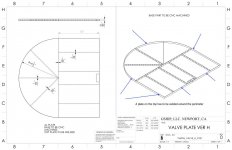
We have a tentative design for either CNC machining and welding 2 sections or welding 3 sections. The challenge is that the thickness of the T 6061 AL we want to use is only 1/32" -- super thin. I'm attaching the drawings of the 2 design choices to see if either or both are possible. If so; how do we keep the aluminum from warping during welding?VARTM_VALVE_H_17MAR2022 ramy welt top and bottom plates 2.jpg
 

Attachments

  • VARTM_VALVE_H_CNC_17MAR2022 ramy weld top.jpg
    VARTM_VALVE_H_CNC_17MAR2022 ramy weld top.jpg
    86.8 KB · Views: 157
  • VARTM_VALVE_H_17MAR2022 ramy welt top and bottom plates 1.jpg
    VARTM_VALVE_H_17MAR2022 ramy welt top and bottom plates 1.jpg
    88.6 KB · Views: 149
First of all, I am not a professional welder. However I do have mig and tig equipment and have used them quite a bit. I have a spool gun for my mig welder and there is no way that would weld something that thin. Tig would be the way to go. I watched a guy at the plant weld two Coke cans together (just showing off) and it can be done. Just my two cents worth.
 
Interesting part. What's the internal design pressure? Also curious how you'll weld the second plate after the frame + first plate are welded together, assuming you also want it welded to the internal structure and not just around the perimeter.
 
You must have heard about TIG welders who brag that they can run a bead down a aluminum thin can.

With a good TIG machine you can dial down to 5 Amps. I am not in the brag bunch.
 
1/32" 6061, GTAW. At that thickness, you can pulse GMAW on very thin aluminum, but we are talking very specialized equipment.
This may be a game changer if it has to be pressurized.
 
Interesting part. What's the internal design pressure? Also curious how you'll weld the second plate after the frame + first plate are welded together, assuming you also want it welded to the internal structure and not just around the perimeter.
Those were exactly the questions that came to me, too!

You might be able to weld the internal structure to both sides using plug welds (basically, drill a hole in the top/bottom immediately over the internal member, then weld the hole shut). But if this thing is to hold pressure, you probably want near-continuous welds to limit the top/bottom spans under pressure. Resistance welding (spot or roller) seems like the only practical solution to me, but 6061 does not like autogenous welds! I.e., it wants filler metal of a different alloy content to avoid hot cracking. If you plan to resistance weld, go with a 5XXX series alloy.

As far as the perimeter welds go, an experienced TIG welder could do this without too much pain, assuming good fitup and fixturing. Give him/her some material to practice with first, to get heat control and travel speed set up! But no human is getting into such deep, narrow recesses to make the interior welds, with any welding technique. Possibly a robot with custom arms and torches.
 
If its 1 or 2 I'd suggest tig
large qty, pulse mig would would be justified
either will most likely require fixturing to hold flat but it may still warp/buckle after removing from said fixture
depending on pressure, adhesives may be a good choice
 
This can be done as drawn but mercy the amount of time it would take me to make sure everything is perfect and not make it into a potato chip wouldn't be worth it if it can be redesigned. On top of that the added dye check for cracks since its holding compressed air.

Honestly looks like a good candidate for furnace brazing to me.
 
I don’t know what that thing does but I’d try to do it another way. If you must use 1/32 aluminum I’d flange it like channel and glue it together. I don’t see it hold much pressure without ballooning out.
 
Internal pressure is 35 psi. We are hoping to be able to do a seam weld around the perimeter. I've heard that Electron Beam Welding is the most precise welding but that TIG will work with a skilled welder. The inside supports will be tacked at a few places along the side and bottom but the top won't be welded inside.
 
It has 40 psi external pressure on it all the time. That is why we are using 35 psi; slightly below the regular pressure.
 
It has 40 psi external pressure on it all the time. That is why we are using 35 psi; slightly below the regular pressure.
This makes a huge difference, and you really should have said that initially. Your problem is now keeping it from collapsing, rather than rupturing, as it's effectively under negative pressure. Just make sure there's no operational transition/condition where that external pressure is released while internal pressure is maintained.

Yes, now the problem of securing the internal members becomes much easier. You don't need near-continuous seams, just enough bonding to keep them from toppling over.
 
Why would the pressure inside create a problem?
What happens to a balloon? Why do pressure vessels have rounded ends, instead of being shaped like tin cans? Because the internal pressure would deform it, possibly even tearing it apart, if it weren't being continuously opposed by the larger external pressure that you just made us aware of.
 
Two alternatives if a glued assembly is acceptable:

Optical benches are assembled with a thin top and bottom plate separated by a light weight core There are a number of companies that will fabricate custom optical benches at a cost significantly less than what it would cost for a do it yourself project. The internal structure will be a aluminum hex grid rather than the handful of ribs shown in your drawing. The hex grid will be lighter and there will be significantly less deflection when the assembly is pressurized compared to your design. The hex grid stiffened epoxied structures have been produced for over 50 years.

The only design limitation that you may encounter is the height of the hex grids available.

A second option is a closed cell foam core with a glue bonded aluminum skin. These panels are a off the shelf item used in assembling walk in refrigerators. A perimeter aluminum strip would need to be glued or welded on after the valve section was cut out of the panel.

There are other options If a glued assembly cannot be used. There is a technique which involves a snap together structure. The lower plate and ribs are machined as a unit. The upper edges of the ribs and perimeter walls have a recessed socket machined in them that will receive the mating top plate interlocking tabs. . The top plate with tabs is machined from a thick plate. This process requires careful inspection of the machined plates and a large press to lock the plates together. The method was patented by Boeing(?) many years ago.


Back
Top