What's new
What's new

XYZ EMill Keeps Cutting Out

BCoyle14

Plastic
Joined
Jul 1, 2022
Hi all,
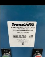
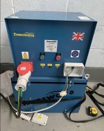
I have just purchased a 2012 XYZ EMill, im using a Transwave 3 phase rotary converter to power the mill.
The issue I have is once the motor is running, it runs for around 1 / 2 mins then the motor cuts out and I have to reset the white LRD box before I can run it again, everything else works still however including the power feed, I’m just unable to start the spindle again until I reset.

This is my first mill and I’m very new to machining, would any of you know why this is or can advise? Could it be possible the transformer is too powerful? Any advice would be greatly appreciated.

Many thanks
Ben
 

Attachments

  • 11AEE470-B99B-4DBE-B192-2C314C976B01.jpeg
    11AEE470-B99B-4DBE-B192-2C314C976B01.jpeg
    487.2 KB · Views: 7
  • 20E7B7D0-579A-4BAB-95FB-6DF3A57A58B0.jpeg
    20E7B7D0-579A-4BAB-95FB-6DF3A57A58B0.jpeg
    295.8 KB · Views: 8
  • 137E6913-E1BF-4885-87F8-83A9C3079C46.jpeg
    137E6913-E1BF-4885-87F8-83A9C3079C46.jpeg
    501.7 KB · Views: 8
  • 1475DC1D-CE95-4038-91E0-2073A500AF8C.jpeg
    1475DC1D-CE95-4038-91E0-2073A500AF8C.jpeg
    392.2 KB · Views: 6
  • AFCDEB58-7F18-4473-AC5E-9AA7609607E3.jpeg
    AFCDEB58-7F18-4473-AC5E-9AA7609607E3.jpeg
    369.9 KB · Views: 5
  • 81C06CD2-1648-4FA9-AC91-8B1B6298359B.jpeg
    81C06CD2-1648-4FA9-AC91-8B1B6298359B.jpeg
    571.1 KB · Views: 7
  • 73BF9AEB-1002-4122-8444-3FBB577BA5B2.jpeg
    73BF9AEB-1002-4122-8444-3FBB577BA5B2.jpeg
    653.7 KB · Views: 8
  • BF667B6F-5665-4FBB-82AC-3A3B61BAD300.jpeg
    BF667B6F-5665-4FBB-82AC-3A3B61BAD300.jpeg
    559.4 KB · Views: 8
  • C8ED48FD-122A-4B70-A4FD-0A556034B117.jpeg
    C8ED48FD-122A-4B70-A4FD-0A556034B117.jpeg
    439.1 KB · Views: 7
That white LRD you singled out in the first pic is a timed overload breaker. Think a regular circuit breaker on a timer, they are used for motors that can start instantly or with a load. example: my old air compressors single phase motor doesn't have a built in thermal overload and uses one. High amp draw on startup till it gets its 14-15" pump pulley going full speed. also a mazak cnc mill at work used the same setup of overload protection on the chip augers for when the auger bound up and stalled the motor. Your motor has to exceed the amps for the time set by the dial (which looks like the arrow is pointed on the 2.5 which could be either minutes or seconds).

Does the motor sound good and smooth and does it do this with the head in neutral or in if the spindle is running in reverse? reason i ask about the reverse is one contact should be for forward and the other reverse. one contact is wired phases A-B-C and the other is wired opposite C-B-A for reversed spindle. ( judging by your diagram with the spindle and coolant motors your having a problem out of the one listed as KM2 the reversing contact). Everything on you control circuit print is on the output side of the transformer and probably not needed since the overload is whats tripping, but the transformer is what sucks in the center button on the contact. if you ever have dead controls, no lights and pw-feed chances are the trans is bad (had a lathe do this, it was only putting out half its step down voltage)

Id take a multi meter measure line to line across the 3 phases at the output of the rotary, the input at the machine (both at the input where the rotary wires come in and where the wires go into the contact the overload is attached to while the mill is off and then while you can briefly get it to run, and also check line to line at the overloads output. at the motor also wouldn't hurt. So you don't have to be at the switch when in the cabinet, take a DRY pair of gloves and a insulated handle Philips screwdriver, you can push and hold the button in the center of the contact to start the motor (flipping the switch at the control will show you what im talking about pushing on the LRD in the pic, the white rectangle button in the center it should suck in when you flip the switch or this will also tell you what the other motor contact is ) . Rule out the electrical first. a missing phase can make a motor sound like its straining/bogging.

Either you have a high amperage draw due to a bad motor or something causing enough resistance to trip the breaker, a bad overload breaker, or a voltage drop/lack of 1 phase (probably the generated leg) and it's causing it to think the motor is overloading. A 3 phase motor can run on 2 phases (like a static phase converter does but they only run @ 2/3 rated HP). This can cause some motors to run a little hotter or draw more amps.

All your other stuff works because when the lines come into the machine they are immediately split to the motor contacts, and the transformer in the bottom of the cabinet that is used to step down for your control voltages and accessory voltage.

sorry if im scattered in explanation.


Hi Roundhouse, thank you so much for this very detailed explanation, it’s everything I was looking for and I can show this to the electrician if I end up needing one. I’m going to test and check what you have said to tomorrow.

It’s probably worth me noting that my coolant system and work light also doesn’t work, with what you have said here I’m wondering if this is something to do with it? Also, if I screw the screw on the LRD a little past the 2.5, then the motor will run without tripping at all. There is no noise or rattles from my motor, it is a very quiet machine and hasn’t had much use in its life as it was an ex university machine.

Thank you again for taking the time to write up such a great explanation

Ben
 
Does your rpc produce balanced/even voltage on all 3 legs? Or does the generated leg run at a higher voltage? I recently encountered a similar problem and pretty sure the problem is the high voltage on the generated leg, and the thermal/o-load switch does not like it. You might be able to solve the problem by moving the generated leg to a different pole on that switch.

If turning the adjustment screw past 2.5 solves the problem, I would try that. NOTE: I am NOT an electrician!
 
Last edited:
Also... according to your wiring diagram, make sure the generated or manufactured leg from your phase convertor is connected to L3. You want that leg to feed motors only. No transformers allowed. If doing this causes your coolant and/or main motor to run backwards, switch L1 and L2 to correct it. This may fix other control issues you're having.


Back
Top