What's new
What's new

Air Compressor Unloader Circuit - How does it work?

RC Mech

Stainless
Joined
Jul 21, 2014
Location
Ontario, Canada
Just finished rebuilding a late-80’s Dresser-LeRoi 660A compressor. Machine was used a storage tank prior to our acquisition, valves in head were broken.

Rebuilt with new bottom-end bearings, crank bearings, piston rings and all gaskets etc. I’ve never heard it run prior to building a control box for it yesterday. Machined new unloader pistons as old units were worn.

Builds air, cuts out at 150 psi per my set points. Unloaders do not work. This is the unloader circuit:
IMG_9057.jpeg

These new copper lines follow the same config as the old. Unloader pistons are in the intake valve caps (duh).
IMG_9055.jpeg

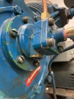
Unloader circuit runs into this unit in front of the oil pump circuit. Plastic line is an oil pressure gauge. Line in front closest to us goes straight into the tank. Air leaks slowly but continuously from this port when pump is stationary:IMG_9056.jpeg

When I plug this port solid, the unloaders are engaged via that “leaking” air pressure. The original plug has a 0.040” orifice in it, designed to leak. #18 on schematic below “plug, orifice for start-stop control only”.

IMG_9058.jpeg

I have no reference for how this is supposed to work. I imagine the unloaders should engage, pump gets to speed, disengage, pumps air. Right now the 10 hp 600V motor powers thru the start up, but then what’s the point of the unloaders right?

How do I plumb this correctly?
 

Attachments

  • IMG_9056.jpeg
    IMG_9056.jpeg
    285 KB · Views: 4
Unloaders are only used when the "power" is not turned off ie: gas engine driving the pump while sandblasting, or the electric motor is not shut off because of very high demand and short cycles.
So the engine/motor keeps on running , a pilot valve senses tank pressure then hits unloaders with air to push intake valves off their seat.
Pressure drops, reverse action....
I have a V4 with unloaders, but the unit cycles the motor on/off so they are not used. Mfg said to just cap them...i guess keep bugs out...lol
 
Fair enough. I was hoping the unloaders would be used in the electric motor case. Since I’ve already got a sizeable electrical enclosure with 120 VAC control side, I’ll put a timer relay and air solenoid in the unloader circuit to kick in the unloaders on start up and load after about 10 seconds.

Might help with the power draw on frequent starts.
 
There are really 2 kinds of unloaders. One releases pressure after the pump stops, so the pump will not have to start under load. The other kind is used for example if the pump is powered by a gas engine which keeps running even when the air tank is full. A pilot valve applies pressure to the intake valves keeping them open so even though the pump is turning over, no air is being pumped.

I suspect the Dresser-LeRoi pump's unloader can be configured either way by the choice of plug. Either the .040" orifice allows pressure to bleed off after the electric motor is shut off or another device applies pressure to the unloader pistons when the tank is up to pressure. Said other device isn't shown.

I suggest you repost the images from the manual, this time including the whole image and also the page where the parts which are called out by number are named.
 
There are really 2 kinds of unloaders. One releases pressure after the pump stops, so the pump will not have to start under load. . .
This is what the OP has. It looks a lot like the one on an old Champion at work. When the oil pressure drops after shutdown the unloader releases pressure. On start up, when oil pressure gets up near normal the unloader closes and pumping starts. It shouldn't be leaking all the time. I had to repair a diaphragm, change o-rings and generally clean things up to get ours working.
 
I'm slightly confused by a lot of the above...but in general the unloader is there (as noted) to unload the pressure in the cylinder so when the compressor is re-started, it is not imposing too much load on the motor.

That said....if the OP's compressor only needs that function, I would think a cheap unloader from a modern, POS compressor would work fine. It's a device that is only active for a few seconds when you shut the compressor off (such as when it reaches the max pressure).

In other words, you could block off or disable all the original unloader parts and fit it with a new unloader assembly.

I also always disconnect the pressure switch from the starting circuit and use it instead to power a 'real' magnetic contactor that is able to handle the amps.
 
Thank you all. The way it works as it sits:

1. Compressor starts loaded when that port is vented to atmosphere. Doesn’t matter if the 0.040” orifice plug is in or port is totally open.

2. Compressor thumps to a stop as if it’s building compression, no “pssst” sound as a typical unloader would make on stop.

If I plug that port entirely while compressor is running, it gets very quiet after 5-10 seconds. Air chuffs out intake, pressure does not build.

I turned all new unloader pistons for it, old ones were worn where they contacted the seals. They must have worked at some point?

When the orifice plug is in, it hisses softly constantly.

Magpie, there is no other device. I’ve been thru this manual, 1988, and a more comprehensive one for a similar 1972 660A pump.

I’ve replaced all orange highlighted parts in the schematic:
IMG_9058.jpeg

Page labelled: Oil Pump Cover

#16 is the Bellofram diaphragm, replaced that. #9 is a Check Valve.

I believe when oil pressure rises, bellofram moves disk piston, pushes square pin/check valve and disengages unloaders. Connected an oil pressure gauge at #3, I have 38 psi after 3 seconds, but unloaders do not engage.
 
In other words, you could block off or disable all the original unloader parts and fit it with a new unloader assembly.

I also always disconnect the pressure switch from the starting circuit and use it instead to power a 'real' magnetic contactor that is able to handle the amps.

That’s what I was thinking, put a relay timer in the electrical enclosure that switches an air solenoid to de-activate the unloaders after 5-10 seconds. But it appears this LeRoi should be doing the same thing mechanically.

Yeah this is a 600V motor 9.9 FLA, run by a heavy contactor with a 120VAC coil. I’ve got the coil wired to the bog-standard pressure switch.
 
Several years ago, I purchased a used Kellogg American two stage compressor sold under the name Henke Pacemaker. It used a fly weight unloader. Unfortunately, the fly weights were destroyed. There were none available from the manufacturer, and there wasn't enough left of them to make copies. I ended up removing all the internals of the unloader system, plugging the air lines and installing a Load Genie self-unloading check valve at the tank.

The Load Genie has been in place nearly 10 years and the compressor works fine. It shuts off at the set point of 135psi and starts at no load when the tank pressure lowers to 75psi. They come in a number of different sizes and can handle up to 48cfm. It might work on your compressor depending on the total cfm output. I was surprised to find Kellog made 15 different versions of my compressor with a wide range of cfm outputs, pressure capabilities, and speed ratings.

Hopefully your serial and model number tags are still attached. A good distributor should be able to use that information to give you the specifics of your compressor.
 
Last edited:
This unloader style also does double duty to protect your compressor if it runs low on oil. Like the Quincy setup, if no oil pressure is developed, the pump will not produce air after anough has been compressed to actuate the unloader system.

It's been awhile, but if I remember correctly, the front facing part of the square pin with the round end seats against the oring to provide the seal which traps the air inside the unloader circuit. When the pump runs, the diaphragm pushes against the puck which pushes the pin backwards and allows the air to escape. It also seals the air signal from the tank. The seal between the pin and oring is critical.
 
The orifice is to delay complete emptying of the unloader circuit to allow the pump to get up to speed before it begins producing air. It helps keeps the inrush current of the motor manageable.


Back
Top