IHateMayonnaise
Aluminum
- Joined
- Jul 17, 2016
- Location
- Albuquerque
Folks,
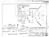
I've been struggling to make sense of this drawing for a 4 degree taper nose common to Hardinge lathes, in particular the HLV and HLV-H. My research has produced no better drawing, cad model, etc. All of my attempts to model the geometry have failed, almost certainly due to my misinterpretations of the drawing below. My questions are embedded in the drawing, along with superimposed lead lines to illustrate the geometry. I have also attached two copies of the original print, note that the PDF is "slightly" higher quality. Any guidance is appreciated...

I've been struggling to make sense of this drawing for a 4 degree taper nose common to Hardinge lathes, in particular the HLV and HLV-H. My research has produced no better drawing, cad model, etc. All of my attempts to model the geometry have failed, almost certainly due to my misinterpretations of the drawing below. My questions are embedded in the drawing, along with superimposed lead lines to illustrate the geometry. I have also attached two copies of the original print, note that the PDF is "slightly" higher quality. Any guidance is appreciated...