What's new
What's new

Delta - Wye Isolation transformer questions. Trying to minimize load on my generated phase. Need help!

mmurray70

Stainless
Joined
Jan 11, 2003
Hey guys Im running my shop with 4 cncs from a 35hp phase converter. We could really use more power but its not an option. We have spindle ramps slowed and we rough our parts a little slower and its working pretty decent but always looking for improvement. Lately ive realized my generated phase has a noticeable drop in voltage when the coolant pump starts on one of the larger machines. Looking at switching the phases around so coolant pump (single phase) is not on the generated phase if possible.

We have a 3 phase delta to wye isolation transformer after the phase converter and im trying to understand exactly what happens to the power after passing through the isolation transformer so i can minimize the load on the generated phase.

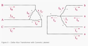
Looking at diagram below lets say A and B is single phase and C is output from phase converter. So A-B and Ib' would be full strength, not generated by phase converter. Is it correct to assume that the only output from the transformer that is not generated by the phase converter would be n-b? So say If I have a machine that uses a 240v single phase coolant pump. I no longer have the option to choose the two wires that produce full power right? I guess b-c or b-a would be best bet? With the coolant pump running from a-c being the worst option? This would be completely run off generated phase right?
 

Attachments

  • Untitled.jpg
    Untitled.jpg
    33.7 KB · Views: 10
Sounds like you've got it.

A presumably sub-HP coolant pump shouldn't cause any noticeable impact on a system that size, though.
 
What is the nameplate rating values of the coolant pump that you suspect of causing the problem, is there more than one single phase coolant pump ?

How about the delta / wye transformer can you supply a photo of the tag? It would also be helpful to see a tag of your phase converter idler motor.
For you to understand better the concepts, you need to realize that there is a difference between phase and line conductors they are not the same. A phase requires two line conductors, one line conductor doesn’t make a phase, it takes two. What that translates to is on the output of your RPC, is you have one utility supplied phase, and two phases that are generated, sharing a output line. A similar thing occurs in your delta / wye transformer. One of the input coils is supplied from the utility power, and the other two are supplied by the RPC.

Then on the three wye transformer output coils one is magnetically paired with a utility powered input coil, the other two output coils are magnetically paired with the two weak generated phase coils. To further exasperate the issue, you need two of those output coils connected together in series to produce the rated output voltage, likely 208V in your case.

When you use a weak generated 208V phase to power a coolant pump designed for 240V, it causes the motor to draw more current than it’s rated 240V, further upsetting the voltage and current balance on the system.

If that is truly what the problem is, it might be best to isolate the power feed to the pump contactor from the transformer output and supply a separate utility powered 240V circuit directly.
 
Thanks for the help so far. Here are more details on my setup as its wired right now, see diagram below. Looks like it might be worst possible combination of wiring on all 3 machines?

The coolant pump on the haas is a single phase 240v 3/4 hp. Starting the coolant pump actually gives a spike of about 30+ amps for split second before it gets up to speed and the voltage on the generated phases drop considerably. Once up to speed it doesnt draw much at all, but i would like to reduce the spike if possible.

So I should swap the wires on the Haas so that the pump uses the black wire right? This would reduce the load on phase converter by half right?

And for the Fadals I should make sure the black wire is feeding the transformer where the 120v power is generated right? Would this mean all the 120v power on the fadals is bypassing the phase converter then?
 

Attachments

  • shop wiring.jpg
    shop wiring.jpg
    176.4 KB · Views: 17
  • 20230529_225242.jpg
    20230529_225242.jpg
    1,019.8 KB · Views: 13
  • 20230529_225207.jpg
    20230529_225207.jpg
    883.4 KB · Views: 17
I switched the fadals over so the black wire generates the 120v and it seems to be very solid now. 120v at the machine doesn't drop under load much at all now so thats great.

And I switched the haas over to use the black and the red on the coolant pump. Red-black seemed to drop less under load then Blue-black so figure this would be best.

Hopefully I did it all right. Glad that all the extra stuff on the fadals now are not putting extra load on the phase converter. Every little bit makes a difference.
 
  • Like
Reactions: SAF
Get yourself a roll of orange electrical tape and identify all of your high leg conductors from the phase converter so that you will always know what conductor is the generated one (high leg) from the converter. This is actually a NEC code requirement, for good reason, on all center tapped delta systems. Which is what a phase converter output is. it is an easy way to prevent mistakes when connecting equipment or repairing existing equipment. Orange is not allowed to be used on any other conductor on a center tapped delta system to prevent confusion. confusing this conductor with either of the other conductors can result in equipment damage or cause operational issues, especially when the circuit conductors are paired with a neutral conductor.

It is bad for drives, VFD or servo when the voltages supplying it are not equal. So always supply single phase loads from the utility supplied lines, never from the orange wild leg.


Back
Top