Mr_CNC_guy
Cast Iron
- Joined
- Jul 29, 2018
- Location
- New England
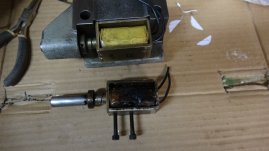
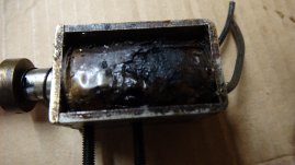
The back-gear lockout solenoid on my '61 modular 10ee was burned out and had been removed. I have the bad solenoid, and it is clearly burned out. I picked up an apparently good solenoid and was going to install it. However, it does not work. Testing the circuitry, there is 120V AC applied to the coil to pull it in. That is controlled by the AP (anti-plug) relay. The solenoid has no copper shorting ring that I can see. That seems to say that it is a DC solenoid.
A solenoid that is going to run on AC must have a copper shorting ring that acts to maintain the magnetic field during the AC sine wave. Otherwise, they will buzz loudly. Relays with an AC coil have a copper shorting ring.
The solenoid measures 2K ohms, so it is not open circuited. I tried using a full wave diode bridge rectifier to drive the solenoid, and it pulled in OK.
This is a mystery! The schematic that I have shows no rectifier for this solenoid. Actually, the schematic glued to the door shows no back-gear solenoid at all, but the lathe did have a lockout solenoid. The schematic that I have that does show the solenoid, but there is no rectifier. I can make this work by adding a rectifier, but I would like to know how it worked originally.


