Howie Dines
Plastic
- Joined
- Sep 17, 2020
- Location
- Germany (Formally UK)
Rather than buying 10” diameter semi-finished back plate, which are quite expensive to buy in Europe. I though It would be nice to make one myself. This way I would not have to compromise with the amount of overhang from the headstock.
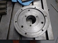
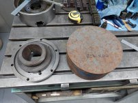
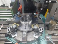
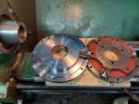
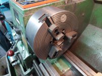
The rear of the chuck showing the 6 outer and 3 Inner allen screws. Due to the threaded rear, the inner 3x screws would need to be fitted from the front. I had a spare piece of steel (Not cast iron) that I planned to use. I wasn’t sure what grade it was, but It did come with a lot of tool steel, and I’m assuming it was actually something like O2 / 1.2842 as it turned out being tough to work with.
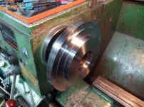
The blank was 230mm Diameter x 110mm weighing in at about 32Kg / 16lb
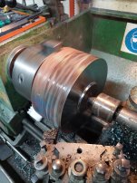
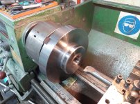
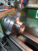
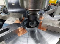
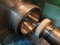
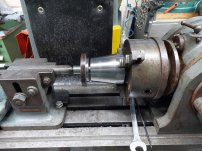
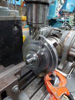
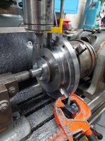
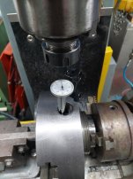
The fun starts on the Colchester master lathe, firstly facing the chuck side and the outer diameter. Flipping in the chuck and then forming the thread blank and internal taper. For this indicating the top slide to the taper on the lathe spindle.
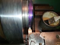
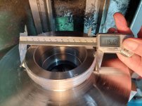
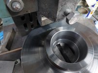
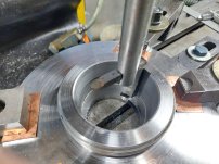
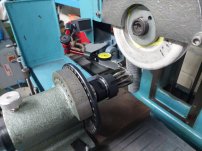
The thread was cut with a HSS hand ground tool. I don’t have a thread pin set so used 3x drill blanks. Machining to match the thread size of the dog plate seen on an earlier picture.
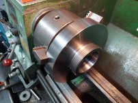
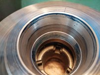
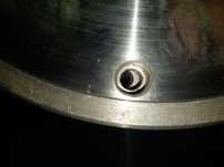
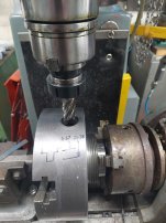
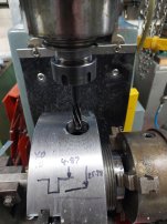
The finished and the blued up taper. Not the best of fits, so I’ll come back to this later after the keyway has been cut.
To be continued ......


The rear of the chuck showing the 6 outer and 3 Inner allen screws. Due to the threaded rear, the inner 3x screws would need to be fitted from the front. I had a spare piece of steel (Not cast iron) that I planned to use. I wasn’t sure what grade it was, but It did come with a lot of tool steel, and I’m assuming it was actually something like O2 / 1.2842 as it turned out being tough to work with.
The blank was 230mm Diameter x 110mm weighing in at about 32Kg / 16lb


The fun starts on the Colchester master lathe, firstly facing the chuck side and the outer diameter. Flipping in the chuck and then forming the thread blank and internal taper. For this indicating the top slide to the taper on the lathe spindle.


The thread was cut with a HSS hand ground tool. I don’t have a thread pin set so used 3x drill blanks. Machining to match the thread size of the dog plate seen on an earlier picture.


The finished and the blued up taper. Not the best of fits, so I’ll come back to this later after the keyway has been cut.
To be continued ......


