Oldmansteve
Plastic
- Joined
- May 12, 2020
Looking for some help with correctly wiring an original instant reversing GE motor. The GE motor # is 5KC63AB776. The relay is # 5099122 BE1.
I have read, re-read, and re-read again every post on this site and the internet in general on the wiring for this motor and relay. But,many of the links in those posts are broken and while they appear they would hold the answer, they are dead links. Yes, I know the relay is an obsolete unobtainable part. Yes I know I could replace the motor and even convert to 3-phase w VFD etc. I do not want to do that. I want to get this going again with what should be an easy fix if someone who has the same components would chime in with a description or pic.
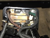
The motor worked normally in forward and reverse when purchased, although I didn't specifically test for instant reverse. Motor was disassembled and reassembled (needed cleaning of caked on oil/dirt etc to cool properly). No wiring was changed. The motor will now not run without hand spin starting. Start capacitor checks out to be okay. Reversing switch wired correctly and clean. I believe the problem is isolated to the relay wiring. Upon inspection of the relay I see the contacts are covered with carbon. I was able to clean one set of contacts, but the deeper set (N/O set) I am unable to get adequate access to, and the contacts are not removable from the plastic housing. But, remember, the motor started and ran fine before removing, despite the carbon buildup in the relay. When initially removing the relay I took pics and found 4 wires from motor to relay box. Green, Yellow, Red, Black.
Red is hard wired to the coil.
Green screwed to the N/C contacts.
Yellow screwed to the N/O contacts.
Black ???
However, the Black wire was found floating in the box and not connected to anything. Black wire has the factory ring terminal on it just like the Gr and Y wires but I have no idea where it goes. So, am hoping someone with the same original motor/relay would be willing to remove their relay cover and snap a pic for me. After playing around with the multimeter a bit, I was able to bypass the relay and get the motor to start and run and reverse by removing the relay completely and using black as common and yellow/red together as the other 120V pole, leaving green completely isolated. But, not sure if that is correct. So, 2 questions:
Thanks in advance.
I have read, re-read, and re-read again every post on this site and the internet in general on the wiring for this motor and relay. But,many of the links in those posts are broken and while they appear they would hold the answer, they are dead links. Yes, I know the relay is an obsolete unobtainable part. Yes I know I could replace the motor and even convert to 3-phase w VFD etc. I do not want to do that. I want to get this going again with what should be an easy fix if someone who has the same components would chime in with a description or pic.
The motor worked normally in forward and reverse when purchased, although I didn't specifically test for instant reverse. Motor was disassembled and reassembled (needed cleaning of caked on oil/dirt etc to cool properly). No wiring was changed. The motor will now not run without hand spin starting. Start capacitor checks out to be okay. Reversing switch wired correctly and clean. I believe the problem is isolated to the relay wiring. Upon inspection of the relay I see the contacts are covered with carbon. I was able to clean one set of contacts, but the deeper set (N/O set) I am unable to get adequate access to, and the contacts are not removable from the plastic housing. But, remember, the motor started and ran fine before removing, despite the carbon buildup in the relay. When initially removing the relay I took pics and found 4 wires from motor to relay box. Green, Yellow, Red, Black.
Red is hard wired to the coil.
Green screwed to the N/C contacts.
Yellow screwed to the N/O contacts.
Black ???
However, the Black wire was found floating in the box and not connected to anything. Black wire has the factory ring terminal on it just like the Gr and Y wires but I have no idea where it goes. So, am hoping someone with the same original motor/relay would be willing to remove their relay cover and snap a pic for me. After playing around with the multimeter a bit, I was able to bypass the relay and get the motor to start and run and reverse by removing the relay completely and using black as common and yellow/red together as the other 120V pole, leaving green completely isolated. But, not sure if that is correct. So, 2 questions:
- I would really like to put the relay back as designed because I do believe it works, but for the life of me I can't figure out where that free black wire with the ring terminal belongs on the relay. Need a pic.
- If in-fact, the relay won't work correctly due to carbon, or later becomes nonfunctional and I need to bypass it, How do I wire the motor? As stated, I found what 'seems' to work, but do not have the knowledge to know if this is correct or if I am going to burn up some windings in short order by doing such. Need some help here.
Thanks in advance.
Attachments
Last edited:


