What's new
What's new

Turning Accurate Tapers - my take on an old task.

Nice trick with the balls!
But I'd use a center drill that is intended for TS-offset work. The don't make a cone, but cut curved "cones".

Also, I don't sweat about trying to exactly offset the TS, but put the bar between centers and sweep the length with a dial indicator (and offset the TS to adjust). Not just that this saves some math (that would not hurt) but it is the most precise setup.
That's the method I use on the cylindrical grinder. And getting the cone right to within 0.01 mm over 200 mm is almost a no-brainer. If you want, you can work your way down to a few µm.

Nick
 
Forrest,

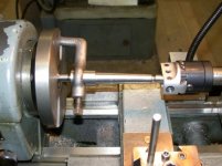
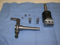
Excellent description of a basic and essential task for the lathe. I also use the 'turn-between-balls' method but I did it a little differently. Here is a brief description and some pics:
tt_setup_between_balls.jpg
Shows the basic setup for turning an MT2.

dscn1015.jpg
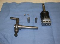
Is all the tooling... except for the center that goes in the spindle.

Basically I used what is obviously an inexpensive boring head with an arbor that fits my lathes tail-stock (in this case an MT2.) I made a couple of "cup" centers. The one for the boring head is shown. It was made from O1 and hardened and annealed to whatever ball-bearings are supposed to be. The other cup center in the lathe spindle is also O1 but not hardened. It mounts in a collet though it could be just as well mounted in a chuck. The reason I did not harden the spindle cup center is it may have to be re-cut each time it is mounted in the spindle. The "cup" centers are just 1/2" nominal O1 with a center hole drilled in them. The head-stock cup center is turned down to fit a 7/16" collet. The HAS to be a shoulder on the head-stock center because if it backs into collet the work can pop out under power. The tail-stock center had to be hardened because I found out that if left un-hardened it got quite hot. All the friction is on the tail-stock center.

There are a few advantages to this setup over what Forrest described in the OP: I don't have to drill any ball-bearings. The use of a boring head makes making fine adjustments a breeze and I can leave my tail-stock alignment un-molested. Otherwise it retains all the advantages of the 'turn-between-balls' method.

To figure out the 'effective length': Cut, face, and center drill the blank. Pop the balls in the center holes. Measure the overall length of the ball-blank-ball and subtract one ball diameter from that measurement and that equals the effective length of the work piece. Now you have correct number for doing the math and dialing the offset of the boring head.

It is VERY important that the work is securely mounted between the centers otherwise it can pop out. Make sure the everything is seated and snugged and the tail-stock is securely locked to the bed.

I have only ever deliberately turned long tapers using two methods. This one and using a regular taper attachment.

-DU-
 

Attachments

  • taper_turning_tools.jpg
    taper_turning_tools.jpg
    29.6 KB · Views: 341
Last edited:
Thanks to both Nxmber and Forrest for explaining the intent of the boring the 60 degree turning center.

I have previously assumed (don't say it, I know) that the center drill will cut "on center". I just never thought to question or check it. I'm going to check with a DTI in the future.

I learned quite a few things today. The good new is that none were associated with a disaster.

Regards,
 
Forrest,

Excellent description of a basic and essential task for the lathe. I also use the 'turn-between-balls' method but I did it a little differently. Here is a brief description and some pics:
View attachment 97273
Shows the basic setup for turning an MT2.

View attachment 97274
Is all the tooling... except for the center that goes in the spindle.

Basically I used what is obviously an inexpensive boring head with an arbor that fits my lathes tail-stock (in this case an MT2.) I made a couple of "cup" centers. The one for the boring head is shown. It was made from O1 and hardened and annealed to whatever ball-bearings are supposed to be. The other cup center in the lathe spindle is also O1 but not hardened. It mounts in a collet though it could be just as well mounted in a chuck. The reason I did not harden the spindle cup center is it may have to be re-cut each time it is mounted in the spindle. The "cup" centers are just 1/2" nominal O1 with a center hole drilled in them. The head-stock cup center is turned down to fit a 7/16" collet. The HAS to be a shoulder on the head-stock center because if it backs into collet the work can pop out under power. The tail-stock center had to be hardened because I found out that if left un-hardened it got quite hot. All the friction is on the tail-stock center.

There are a few advantages to this setup over what Forrest described in the OP: I don't have to drill any ball-bearings. The use of a boring head makes making fine adjustments a breeze and I can leave my tail-stock alignment un-molested. Otherwise it retains all the advantages of the 'turn-between-balls' method.

To figure out the 'effective length': Cut, face, and center drill the blank. Pop the balls in the center holes. Measure the overall length of the ball-blank-ball and subtract one ball diameter from that measurement and that equals the effective length of the work piece. Now you have correct number for doing the math and dialing the offset of the boring head.

It is VERY important that the work is securely mounted between the centers otherwise it can pop out. Make sure the everything is seated and snugged and the tail-stock is securely locked to the bed.

I have only ever deliberately turned long tapers using two methods. This one and using a regular taper attachment.

-DU-

It's critical that the tail stock center is at spindle height (relative to the ways). Assuming that both centers have same OD, I'm thinking put a DTI on the carriage and check both center heights (indicate top or bottom of OD) before making chips. I think that would be more accurate than using a level on the boring head.

How do you recommend verifying the height of the center in the boring head?
 
Forrest,

Excellent description of a basic and essential task for the lathe. I also use the 'turn-between-balls' method but I did it a little differently. Here is a brief description and some pics:
View attachment 97273
Shows the basic setup for turning an MT2.

View attachment 97274
Is all the tooling... except for the center that goes in the spindle.

Basically I used what is obviously an inexpensive boring head with an arbor that fits my lathes tail-stock (in this case an MT2.) I made a couple of "cup" centers. The one for the boring head is shown. It was made from O1 and hardened and annealed to whatever ball-bearings are supposed to be. The other cup center in the lathe spindle is also O1 but not hardened. It mounts in a collet though it could be just as well mounted in a chuck. The reason I did not harden the spindle cup center is it may have to be re-cut each time it is mounted in the spindle. The "cup" centers are just 1/2" nominal O1 with a center hole drilled in them. The head-stock cup center is turned down to fit a 7/16" collet. The HAS to be a shoulder on the head-stock center because if it backs into collet the work can pop out under power. The tail-stock center had to be hardened because I found out that if left un-hardened it got quite hot. All the friction is on the tail-stock center.

There are a few advantages to this setup over what Forrest described in the OP: I don't have to drill any ball-bearings. The use of a boring head makes making fine adjustments a breeze and I can leave my tail-stock alignment un-molested. Otherwise it retains all the advantages of the 'turn-between-balls' method.

To figure out the 'effective length': Cut, face, and center drill the blank. Pop the balls in the center holes. Measure the overall length of the ball-blank-ball and subtract one ball diameter from that measurement and that equals the effective length of the work piece. Now you have correct number for doing the math and dialing the offset of the boring head.

It is VERY important that the work is securely mounted between the centers otherwise it can pop out. Make sure the everything is seated and snugged and the tail-stock is securely locked to the bed.

I have only ever deliberately turned long tapers using two methods. This one and using a regular taper attachment.

-DU-

David, I'm a bit puzzled by your taper tooling picture. I see one ball center but the other looks like a regular center to me. And neither looks like it has a shoulder. Does that picture show every piece you used in the machining pic, and nothing else?

metalmagpie
 
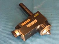
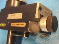
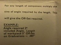
Royal used to sell an English-made taper attachment with MT2 shank and ball-tipped live center. It came with a chart. Here are pictures, but I do not have the attachment, which was expensive and now very rare.

Larry

Royal Taper Attachment Chart 001.jpgRoyal TaperAtt 1.JPGRoyal TaperAtt 2.JPGRoyal TaperAtt 3.JPG
 
There are a few advantages to this setup over what Forrest described in the OP: I don't have to drill any ball-bearings. The use of a boring head makes making fine adjustments a breeze and I can leave my tail-stock alignment un-molested. Otherwise it retains all the advantages of the 'turn-between-balls' method.

That's very nice in that you don't need to offset the tailstock, very slick.

Thanks for sharing Forrest, you are always full of clever ideas, and this is yet another one I wasn't aware of. :)

Cheers,
Alan
 
It's critical that the tail stock center is at spindle height (relative to the ways). Assuming that both centers have same OD, I'm thinking put a DTI on the carriage and check both center heights (indicate top or bottom of OD) before making chips. I think that would be more accurate than using a level on the boring head.

How do you recommend verifying the height of the center in the boring head?

Good question extropic. The way I did it was using a DTI. Since both centers are made from the same diameter stock (1/2" O1 round)... I pop the tail center in an outer hole (closest to the front of the lathe/operator), then zero a DTI on the headstock center that is mounted from my toolpost*, then crank the carriage over to where the boring head is and then indicate on the center in my boring head, at this point the boring head shank is not fully seated in the tailstock ram. I have about a foot of 1/2" rod as a tommy bar sticking out the back side of the boring head (gives me nice fine leverage on positioning the angle of the boring head with respect to the bed.) Snug all clamps on the tailstock-to-ways and tailstock ram and tweak my tommy bar until I get zero on the DTI again and give it tap on the nose with a plastic faced mallet to seat the taper in the tailstock ram. I would guess I get between +/- 0.001 and 0.002" height difference between the two centers. Which is plenty good enough for an MT2 taper accuracy IF the tool tip is set to centerline height with as much care.

I did-the-math (as it were) for a quick analysis of how much variation in centerline between centers and tool tip height affects the accuracy of the taper generated and it works out that on the diameters for an MT2 (about 1/2" to 3/4" range) a variation of as much as +/- 0.010 in tool tip and/or centerline height leads to an error of +/- 0.0002 on the small end. On the big end it is in the millionths. With my method of careful setup (+/- 0.002") the variation is in the millionths at the small end. So, um close enough.

Note: On the picture that LVanice posted of the Royal adjustable tailstock center they have a small level via installed. I would guess that it is good enough for setting the fixturing accurately.

*Note also: In my first pic you can see a rod sticking straight up out of my shopmade quick change toolpost. That was installed there for easy mounting/dismounting of a DTI. It is standard 5/16" diameter rod. I found the arrangement so handy that I installed a similar rod in the white lead hole (after tapping) of the tailstock. That is where I keep the DTI for the lathe mounted when not in use. I also made a similar mount for the same indicator on my mill for quickly tramming in a vise or work piece. It is quicker in most situations for mounting a DTI than getting out the right clamps, snugs, rods, and magnetic bases every time I want to dial something in. I use my DTI a lot to check things because it is so easy to do :D

-DU-
 
A 3/8" ball contacts a 60 degree cone on a 0.328" dia.

I cut and pasted Forrest's post thinking I'd really read it when I had time. Well, time passed. Recently, however, I was on a hot dusty bus going across an empty African desert, and I had quite a bit of time to think. I decided to rigorously go through his post.

I tremble to say this, being as Forrest has forgotten more about machining than I've ever known. But I just don't see 0.328" as the correct chord length wherein a 3/8" ball intersects a 60° cone. I get 0.325" every single time. It's just the radius of the ball times the square root of 3. I have a drawing where I calculated this, but for some reason I can't FTP to my own web site at the moment, so you'll have to rederive it if you want to check my math. (sorry!)

Make your center-drilled center preps accordingly.

I find this bit to be confusing. Does he mean center drill your part so that the largest diameter of the center hole equals 0.328"? Or does he mean center drill so the largest diameter of the hole is larger than 0.328"?

Anneal some 3/8” dia balls salvaged from a defunct bearing. Grip them one by one in a collet and center-drill 5/16” full depth and with a dinky little boring bar tool out the conical recess to clean up.

Again I'm confused. Does "center-drill 5/16" full depth" mean use a no. 4 center drill (which has a 5/16" body diameter) and plunge it in until the largest diameter of the center hole is 5/16"? Because 5/16" is 0.3125" which is narrower than his 0.328" above (or my 0.325", for that matter). It seems to me it would make more sense to use a no. 5 center drill which has a 7/16" diameter body, and drill it slightly larger than 0.328" so the ball seats solidly in it.

metalmagpie
 
I cut and pasted Forrest's post thinking I'd really read it when I had time. Well, time passed. Recently, however, I was on a hot dusty bus going across an empty African desert, and I had quite a bit of time to think. I decided to rigorously go through his post.

I tremble to say this, being as Forrest has forgotten more about machining than I've ever known. But I just don't see 0.328" as the correct chord length wherein a 3/8" ball intersects a 60° cone. I get 0.325" every single time. It's just the radius of the ball times the square root of 3. I have a drawing where I calculated this, but for some reason I can't FTP to my own web site at the moment, so you'll have to rederive it if you want to check my math. (sorry!)


I find this bit to be confusing. Does he mean center drill your part so that the largest diameter of the center hole equals 0.328"? Or does he mean center drill so the largest diameter of the hole is larger than 0.328"?


Again I'm confused. Does "center-drill 5/16" full depth" mean use a no. 4 center drill (which has a 5/16" body diameter) and plunge it in until the largest diameter of the center hole is 5/16"? Because 5/16" is 0.3125" which is narrower than his 0.328" above (or my 0.325", for that matter). It seems to me it would make more sense to use a no. 5 center drill which has a 7/16" diameter body, and drill it slightly larger than 0.328" so the ball seats solidly in it.

metalmagpie

By my calculation you are correct.

As regards your queries, for #1 I believe Forrest was saying to be sure that the big end of the center drilled hole was larger than the diameter that the ball seats at, so that the ball contacts the cone at a point inside the plane of the workpiece's end.

For query #2 I believe Forrest meant to use a number 4 center drill to full depth, then take a few passes with a small boring bar to tool the center cone until large enough to satisfy #1. You could alternatively use the #5 center drill as you've described but it won't likely be as accurate in terms of true center.


Back
Top