How to install the app on iOS
Follow along with the video below to see how to install our site as a web app on your home screen.
Note: This feature may not be available in some browsers.
Largest Manufacturing Technology Community on the Web
Stay Connected:
You are using an out of date browser. It may not display this or other websites correctly.
You should upgrade or use an alternative browser.
You should upgrade or use an alternative browser.
First image attempt, and shaper question
- Thread starter SB '55
- Start date
- Replies 36
- Views 3,772
![sbshaper0080.JPG[IMG]](http://www.metalworking.com/DropBox/sbshaper0080.JPG[IMG])

Amazing what a backslash will do for ya...
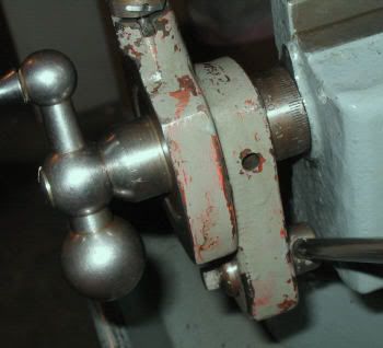
Now, I'll bet somebody (like Paula) will see something wrong in this picture of a SB shaper toolhead, as I received it.
Got a few questions, if anybody here is familiar with these nifty little machines.
Mike
Now, I'll bet somebody (like Paula) will see something wrong in this picture of a SB shaper toolhead, as I received it.
Got a few questions, if anybody here is familiar with these nifty little machines.
Mike
Paula
Titanium
- Joined
- Sep 16, 2005
- Location
- Indiana, USA
Okay, I'll play along.Now, I'll bet somebody... will see something wrong in this picture of a SB shaper toolhead, as I received it.

This is quite interesting, because just last night I pulled the tool slide off my SB7 (mostly out of curiosity), and right away I knew exactly what your picture was.
Let's see... for one thing, the threaded portion of your feedscrew seems to be abnormally long. For another, the feedscrew shank, index collar and handle seem to be AWOL. Is this the way it came?

Paula
There you are, Paula. I was hoping you'd check in.
Yes I got it this way. Don't know for sure, but I think it was an attempt at a repair or replacement by somebody with not enough understanding of how the thing works. Rest of the machine is pretty sound, though.
The main question I have is: Does your toolhead casting have threads in the hole where the conical boss is--that is, the place where the graduated dial sits?
I have the ball crank, but until I sort out all the parts for the crossfeed auto crank mechanism, I won't be sure what goes where, and whether I have the graduated dial. The line drawings in the Army manual are not distinct enough to tell.
I wonder if you would be kind enough to post some pics of the toolhead, and also of the feed crank mechanism? That would help me a lot in sorting out the parts. There's more to this, but I'm late getting out as it is. I'll get back with more this evening.
BTW, Paula, I thought my restoration of a 9A HD looked good until I saw yours. Very nice!
Thanks,
Mike
So, to continue, this puppy has threads in both ends of the unit. Turning the length of raw acme rod simply runs the rod in and out of the unit, without moving the base relative to the upper casting.
I guess what I'm trying to find out is whether (as I assume) somebody either tapped the end of the body casting, or pressed in a turned acme nut. Looking at the drawing I have, the original feed screw design looks just like the one in a 9A compound, and that means that the end that goes thru the upper end of the slide casting should be a smooth cylinder with a shoulder to bear on the boss inside the casting.
Once I verify that this is correct, then it won't be such a big deal to make a screw from scratch. In an unusual lucky coincidence, shortly before acquiring the shaper I was getting some practice at this by making new bronze nuts, feed screws, and larger graduated dials for the 9A. All I need is to know which way to jump.
Paula
Titanium
- Joined
- Sep 16, 2005
- Location
- Indiana, USA
Hi Mike,
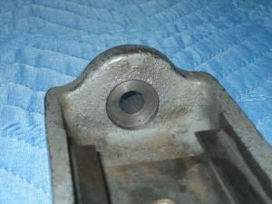
Since I had the tool slide off of my shaper, I snapped a few pictures before reassembling it. Your guess was pretty much on target about the feedscrew -- typical South Bend design -- very simple. The first picture shows the inside of the slide casting. Just a smooth bored hole, and a shallow counterbore. The next picture shows the feedscrew parts disassembled. Like you said, almost identical to the lathe compound setup.
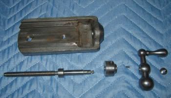
Let me know if you could use any other pics. I took several close-ups of the cross-feed mechanism. If that piece of Acme threaded rod is the right size, you could possibly use it to make a composite feedscrew. Let me know if you would like the dimensions of the feedscrew.
Paula
Since I had the tool slide off of my shaper, I snapped a few pictures before reassembling it. Your guess was pretty much on target about the feedscrew -- typical South Bend design -- very simple. The first picture shows the inside of the slide casting. Just a smooth bored hole, and a shallow counterbore. The next picture shows the feedscrew parts disassembled. Like you said, almost identical to the lathe compound setup.
Let me know if you could use any other pics. I took several close-ups of the cross-feed mechanism. If that piece of Acme threaded rod is the right size, you could possibly use it to make a composite feedscrew. Let me know if you would like the dimensions of the feedscrew.
Paula
Thanks, Paula.
That was just what I needed. The guy did in fact press in a threaded ring. I bored it out last nite, and will now plan to make a replacement screw.
If you would be kind enough to let me know the distance from the left tip of the screw (as oriented in your photo) to the right side of the ring that bears on the underside of the casting's counterbore, that would be a great help. That, and the thickness (axially) of the ring are the only dimensions I can't work out on the basis of what I have here on hand.
If you get the chance and are so inclined, pics of the auto-crossfeed crank assembly would also clear up a few questions about how the former owner put this one together. Please don't trouble yourself to disassemble anything. A shot of it from the front or rear as it sits on the machine will probably do it.
Thank you for your time and effort. It has been a great help.
Mike
Just for the heck of it, this is the compound feed unit for the 9A in progress:

The back of the graduated dial has not been contoured yet, so that it can be more firmly fixtured for the number engraver, and the crank end of the screw has not been turned down and threaded for the capture nut. This will all be done to fit after the dial is final contoured.
Mike
The back of the graduated dial has not been contoured yet, so that it can be more firmly fixtured for the number engraver, and the crank end of the screw has not been turned down and threaded for the capture nut. This will all be done to fit after the dial is final contoured.
Mike
Paula
Titanium
- Joined
- Sep 16, 2005
- Location
- Indiana, USA
Very nice work on the compound parts, Mike. I've done a bit of that type of work myself in the past and always found it very rewarding. I may yet make some larger feed dials for my 9A.
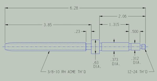
Here is a drawing of the tool slide screw. There are some dimensions there that you had not asked for, but I thought might be useful to someone else, while I was at it.
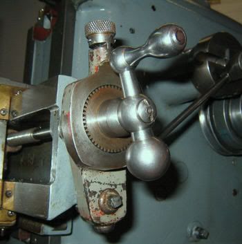
Here are a couple views of the cross-feed mechanism:
Hope this information is helpful.
Paula
Here is a drawing of the tool slide screw. There are some dimensions there that you had not asked for, but I thought might be useful to someone else, while I was at it.
Here are a couple views of the cross-feed mechanism:
Hope this information is helpful.
Paula
Last edited:
That is just the ticket, Paula. I already see an assembly error that I suspected, verified in your photos.
You have been very generous to me in your time and effort in this matter, and I want to give you my heartfelt thanks.
Some time in the not too distant future, I'll post some shots of the finished product.
Best wishes,
Mike
You have been very generous to me in your time and effort in this matter, and I want to give you my heartfelt thanks.
Some time in the not too distant future, I'll post some shots of the finished product.
Best wishes,
Mike


Paula
Titanium
- Joined
- Sep 16, 2005
- Location
- Indiana, USA
Looking good, Mike!

Looks like a new machine. I'm assuming you re-painted. Did you repaint the red oxide areas, too? I notice you have one of the original-type tool holders there. (I saw one go for nearly $100 on Ebay recently!) I'm also envious of your on/off switch, as mine was missing when I got the shaper.
Thanks for posting the pictures.
Paula
P.S.- I see your 9A there in the background. What did you wind up doing about your worn spindle/bearings?
Wow! You have a good memory.
Regarding the lathe spindle bearings, I'm sure this will horrify the non-amateurs out there, but but I just used a 600-grit and then crocus cloth, wrapped around a slightly undersized bronze bushing that I used as a mandrel, and carefully dressed down the high spots in the gouged areas in the headstock bores. I also polished down the highest irregularities on the spindle journals, being careful to do no more than the minimum I judged as necessary. I then made up new shim packs, adjusting them and the pinch bolts until I got into the vertical play zone that everybody recommended. It's run fine for the year and a half since, although I checked it recently and it's "worn in" a couple of thousandths, and will need to have the shim packs adjusted again. It'll still turn pretty well, and I have not too much trouble holding a .001 tolerance (I've learned that a lot of that is tool geometry and keenness), but I wouldn't want to have to work to aerospace tolerances.
One of the projects I have for the near future is to find another headstock casting with a thrashed bearing area (suitably cheap), and try making up a toolholding shaft to run between centers to line bore a new seat for some bronze bearing rings. Seems to me that line boring on my own ways ought to get the bores lined up perfectly for my machine, but I could be wrong about this.
All in all, I can't complain, considering that I got the machine with threading dial and a collet set and drawbar for 200 bucks (albeit in a sorry condition). I've had a lot of fun with it, and learned an unbelievable amount of stuff since. What really blows me away is the realization of how much I DON'T know yet, and will probably never live long enough to learn.
Speaking of sorry condition, here is what the worst side of the shaper looked like as I received it, more or less mechanically sound, but the victim of neglect, and possibly an electrical fire in the side-mounted junction box:

The strangest thing is that after searching for one for six months, and all of them being over 1200 miles away, I found this one literally ten minutes from my house. Go figure.
Best regards,
Mike
Regarding the lathe spindle bearings, I'm sure this will horrify the non-amateurs out there, but but I just used a 600-grit and then crocus cloth, wrapped around a slightly undersized bronze bushing that I used as a mandrel, and carefully dressed down the high spots in the gouged areas in the headstock bores. I also polished down the highest irregularities on the spindle journals, being careful to do no more than the minimum I judged as necessary. I then made up new shim packs, adjusting them and the pinch bolts until I got into the vertical play zone that everybody recommended. It's run fine for the year and a half since, although I checked it recently and it's "worn in" a couple of thousandths, and will need to have the shim packs adjusted again. It'll still turn pretty well, and I have not too much trouble holding a .001 tolerance (I've learned that a lot of that is tool geometry and keenness), but I wouldn't want to have to work to aerospace tolerances.
One of the projects I have for the near future is to find another headstock casting with a thrashed bearing area (suitably cheap), and try making up a toolholding shaft to run between centers to line bore a new seat for some bronze bearing rings. Seems to me that line boring on my own ways ought to get the bores lined up perfectly for my machine, but I could be wrong about this.
All in all, I can't complain, considering that I got the machine with threading dial and a collet set and drawbar for 200 bucks (albeit in a sorry condition). I've had a lot of fun with it, and learned an unbelievable amount of stuff since. What really blows me away is the realization of how much I DON'T know yet, and will probably never live long enough to learn.
Speaking of sorry condition, here is what the worst side of the shaper looked like as I received it, more or less mechanically sound, but the victim of neglect, and possibly an electrical fire in the side-mounted junction box:
The strangest thing is that after searching for one for six months, and all of them being over 1200 miles away, I found this one literally ten minutes from my house. Go figure.
Best regards,
Mike
walter west
Cast Iron
- Joined
- Jan 21, 2002
- Location
- grand haven,mi., USA
Paula, interesting you mentioned an original cutting tool holder that you did not get and that one on ebay went for $ 100. Years ago I had both an Atlas 7" and at a yard sale got a Southbend Like yours with the base cabinet for an unbelievely low price.Unfortunately had to fire sale both and got a very low price. A few years ago I saw an ad that said 6" shaper for sale. I didn't know of any 6" metal shapers or wood shapers listed in sizes. Had to see it. It turned out to be a 7" Atlas with the cast iron legs base and original motor. And guess what it had an original cutting tool like you mentioned all for a can't not buy price of $ 100. I burnt the edges of the money getting it out of my wallet.
Since I was building my own house I did not get to use it and found at a high school sale my dream shaper, a Sheldon 12" in good condition with all the options at another can't not buy price. I bought it and the Atlas toolholder was to small , so I ebayed it almost for the cost of total Atlas shaper. Probable sell the free one next spring.
Walt
Paula
Titanium
- Joined
- Sep 16, 2005
- Location
- Indiana, USA
Wow, reading about the deals you guys have gotten reinforces my belief that, when it comes to old machines and accessories, eBay is for sellers, not buyers.

Paula
Paula
ltvTom
Plastic
- Joined
- May 22, 2003
- Location
- Fairview Park,Ohio USA
SB '55 In case you or anyone else needs it, here is a link for the South Bend 7" Shaper (Army manual) 43 page pdf file.
http://www.kinzers.com/don/MachineTools/techman/sbarmy7shaper.pdf
Tom
http://www.kinzers.com/don/MachineTools/techman/sbarmy7shaper.pdf
Tom
Thanks, Tom.
I also found it on the excellent WEWilliams.net site.
Paula, I saw that toolholder, too. I was going to bid on it, until it got past fifty bucks. Because of both rarity and price, I've resolved that I'm going to have to make my own holders for bars and such. The good news is that the shaper should make this easy.
One thing I'm not up to speed on: Some drawings and pics show a ring under the toolholder shank, like the "lantern" setup on a lathe, and some show the shank sitting directly on the clapper. The manual mentioned by Tom shows the ring in the parts drawing, but as I've noted before, the line drawings are not distinct enough to get much detail.
So, the questions are: Should I be running a ring under the holder shank, or does it matter, and; is the ring a flat ring, or is it dished with a wedge like the lathe setup?
[ 02-05-2006, 11:26 PM: Message edited by: SB '55 ]
Similar threads
- Replies
- 2
- Views
- 320
- Replies
- 3
- Views
- 471
- Replies
- 1
- Views
- 596
- Replies
- 10
- Views
- 579