What's new
What's new

External M Code Mori NL2000

Mr.Chipeater

Aluminum
Joined
Apr 20, 2021
I was hoping someone might be able to provide some insight into how I can go about wiring in another pump to turn on/off with an M code.

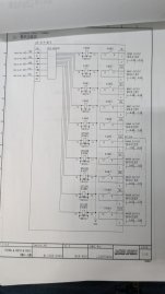
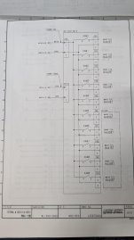
Our machine has the external M code option with the break out board in the electrical cabinet but it looks like all the codes require an MFIN signal to continue otherwise the control just sits on that line in the program.

What does the MFIN need to be and how do I give it one with just an AC pump? Or is there some way around the requirement? I don't see a spare latching M code (like how M08/M09 works).

I called Mori and the guy pretty much said I'd have to call service and have them come out to wire it in which seems silly given we already paid of the external M codes when we bought the machine.
 

Attachments

  • 1000012590.jpg
    1000012590.jpg
    178.5 KB · Views: 9
  • 1000012591.jpg
    1000012591.jpg
    157 KB · Views: 10
What does the MFIN need to be and how do I give it one with just an AC pump?
If a FIN signal was needed, you would want a 24VDC connection to one post of a NO switch mounted or integral to the Pump Motor Start Relay. The other side of that switch would go to an X Input. You can steal the 24VDC that will be there already to drive the coil of the Motor start Relay.

Sorry that's only the bare bones of it. The what X input and how does that become, (or where do you find) a FIN input is beyond my capabilities without a pile of electrical manuals in front of me.

Hopefully smarter folks then I will have the answer to "where do I connect this one wire?" And... "are there any bits to be flipped too?"
 
If a FIN signal was needed, you would want a 24VDC connection to one post of a NO switch mounted or integral to the Pump Motor Start Relay. The other side of that switch would go to an X Input. You can steal the 24VDC that will be there already to drive the coil of the Motor start Relay.

Won’t quite work that way in most cases. The MFIN signal should just be a momentary pulse. If it is continuously held on then any subsequent M code that is executed that uses an external MFIN will be seen to be “finished” immediately. Depending on what that subsequent M code’s function is the results could be a problem. The machine builder’s ladder can have some control over this behavior so it won’t be true in all cases but one would need to have a close look at the logic to determine how to best implement MFIN for a given machine. I have done several machine mods where a timer relay had to be used to provide the appropriate MFIN signal.
 
Won’t quite work that way in most cases. The MFIN signal should just be a momentary pulse.
That did cross my mind at one point.

If he had a pair of M codes at his disposal, he might be able to do like I did in a Probe On/Off subroutine called by M code. I simply stuck a G4P5 in between the on and off M codes. Wonder if it could be applied here? Though except to read the M codes and supply the 24V, I was mostly talking to a Renishaw MI 12 Interface.
I have done similar when retrofitting a probe to machines that did not have logic specific to a probe interface. Many builders include logic for M codes for clamp/unclamp a 4th axis that in many cases I have been able pirate those for a probe since machine was not equipped with the 4th. This technique also had been used for skip signal switching between a part probe and tool probe on field installs where no proper interface existed.
 
Is there any way to change them over to latching M codes or have them function as pseudo latching? I have familiarity with that so it would be rather straight forward to me but why Mori decided every extra external M code requires a MFIN signal is beyond me.
 
Is there any way to change them over to latching M codes or have them function as pseudo latching? I have familiarity with that so it would be rather straight forward to me but why Mori decided every extra external M code requires a MFIN signal is beyond me.
That’s why I posted previously to look through the ladder documentation for a keeprelay or Data address to see if your ladder has options on how extra M codes behave. Even if there isn’t, it’s not hard to make a circuit with a timer relay to generate MFIN.

Mori folks writing the ladder understand that while it’s a little extra work for when you need to fake an MFIN, while there is no easy reliable workaround when you need an M code to wait for MFIN and the M code doesn’t.

Depending on your control you may have ladder editing ability. If it really feels like too much effort to add a timer relay to fake MFIN, then mod the ladder.
 
I don't think the OP realizes how lucky he has it to have a Spare M Code Option installed. The connection points for all the spare M codes must be on a DIN rail or something similar. One can only dream of such easy accessibility. Likely no need to add pins to existing connectors or anything.

Mori Options tend to have documentation concerning them in the back pages of the Electrical or Ladder manuals. Something like a Spare M code Option might even have a separate book or info in one of the Operations or Maintenance Manuals.

If the reason you have the Spare M Code Option is because the machine came with a few already activated for special needs, find those M codes in the Electrical Manual. They'll tend to be listed all right after each other. Hopefully the ones that were installed are correctly depicted (connected) in the manual. Just use what you see there as a guide to connect one of the "empty" or unconnected circuit depictions for the as yet unused M codes listed. Most likely on the same page or the one following.
 
The pictures I attached to my original post are from the "Specifications for option of electric drawing - external M codes" Apart from what I posted, it has a parts lists but nothing else. I don't believe we have the ladder documentation either.

I found the relays in the electrical cabinet no problem and see where to make the connection. The only thing I'm missing is the MFIN signal and I'm not seeing much help in the electrical drawing on how to implement it.
 
Ok so if we focus on just a single M code for right now, say M441:

When M441 is active, pins 1 & 2 join together and pins 3 & 4 show 24V.
When reset, pins 1&2 are broken and pins 3&4 show 0V.

Am I to take the 24V from pin 3&4 to connect it to X70 MFIN?

I have a pump on its own relay with a breaker. I can use the 24V output to activate the pump relay which seems straight forward but I'm still confused on the the MFIN part.

1713468981079.png

PXL_20240418_193955777.MP~2.jpg
 
With the images I can help design a circuit for you to run a coolant pump. Before I do that I need to know how the M codes behave. When you execute M441, the relay KAM1 should turn on and the control should hang. Then when you momentarily place a jumper across terminals 3 and 4 does the relay KAM1 turn off or stay on?

Which M code do you plan to use to stop the pump?

Is your pump 3 phase or single phase. What is the coil voltage of the relay or contactor you plan to drive the pump with? Is there 1 or 2 auxiliary contacts on that relay or contactor?
 
Last edited:
With the images I can help design a circuit for you to run a coolant pump.

I look at images on the screen and my mind can't put things together like it can when the printed page is in front of me. Probable explains why I didn't recall the original pictures the OP posted out of the manual, which I had tried to tell him to find. (Head slap)

Good luck on this... should be an easy deal. I would kill for an M-code board like that. With documentation even!
 
With the images I can help design a circuit for you to run a coolant pump. Before I do that I need to know how the M codes behave. When you execute M441, the relay KAM1 should turn on and the control should hang. Then when you momentarily place a jumper across terminals 3 and 4 does the relay KAM1 turn off or stay on?

Which M code do you plan to use to stop the pump?

Is your pump 3 phase or single phase. What is the coil voltage of the relay or contactor you plan to drive the pump with? Is there 1 or 2 auxiliary contacts on that relay or contactor?

When I execute M441, relay turns on, control hangs. Then if I jump pins 3 and 4, the relay turns off and the control continues.

The pump is a 208V 3 phase. I plan on getting the power directly from the lines coming into the machine and I've attached a pic the pump relay that came with the pump.

Given the KAM1 relay turns off, it looks like I'm going to need a different pump relay that will stay closed from a pulse signal. Then use a 2nd M code pulse to shut it off. Does that sound right? Shame it just doesn't stay on.

1000012615.jpg
 
Is the coil voltage on your pump relay 120VAC? Does it have any auxiliary contacts?
so the pump is being scavenged from another machine that no longer uses it. It had its own separate box that I was going to repurpose to work with the Mori.

Probing around, 208V comes in, goes through the fuses then into the top of the relay. From the relay, it goes into a breaker, then to the pump. I didn't find 120V on the relay anywhere.
PXL_20240423_171435271.jpg
 
Ok, so I've figured out how to use the M code to turn on a relay to actuate the 120V contactor which turns on the pump. My problem now is how do I get the pump to stay on when the MFIN signal shuts off the external M code relay?

I could buy a latching relay but then reset won't shut it off, only another using a 2nd M code will which I feel is a safety hazard.
 
Latching relay is not good also because if the relay is latched on and the power goes out, the pump would turn back on as soon as the machine was restarted. Typically you would use an auxiliary contact of the main pump relay wired in an or configuration to hold the coil energized once the M code is reset. See the attached PDF for an example. Unless there is an output for external reset signal provided in your schematic, Reset will not be able to be used to turn this off, only M442. One could add a NC push button in the latching rung to manually turn off the pump.
 

Attachments

  • VISIO-Drawing1 (2).pdf
    117.7 KB · Views: 2
Another method would be to "rob" another M code. Often M7 or M50 are provided as alternate coolant signals. If your machine has those but they are not utilized in your configuration, you may be able to use one of them.


Back
Top