kmsorensen
Plastic
- Joined
- Oct 24, 2017
An alternate title for this post could be “42’ Round Dial Apron Assembly for Dummies”. To be clear, the dummy is me. I’m pretty inexperienced and the material in this and any following posts is nearly all gleaned from this Monarch Forum.
This is about refreshing Monarch 10EE Round Dial serial number 16238 which came off the line in October 1942. I’m starting with the apron.
See attached images.


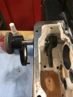
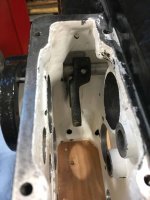
The second image shows the parts that came out of my apron after cleanup and prep for assembly. The first is the same image with parts numbers that more or less parallel part numbers from the page named
“Parts Picture No. E-6 APRON”
as seen in the “OPERATOR’S MANUAL for MONARCH MODEL “EE” SENSITIVE PRECISION TOOL MAKER’S LATHE”. The Operator’s Manual is available on line as a PDF and is also the manual Monarch supplied me when I bought a manual for my machine from them.
The parts shown in my image and in the Monarch Manual are nearly all the same, but there are some differences. I have below short descriptions of some of the labeled parts in image 1, and comments that might be helpful if you’re planning to take your apron apart. I’m planning to continue the post to include a complete assembly of my apron and I’ll refer to these parts numbers in later posts. One could use this series of posts backwards as one possible way to take an apron apart.
Parts 5,6 & 7, I left assembled. These with parts 8 & 10 comprise the Handwheel Clutch.
Part 9 “Wormwheel shaft Snap Ring. I believe this is a misprint in the manual. I believe this is the Handwheel Shaft Snap Ring.
Parts 14 & 16 I left assembled. This combination drives the Bijur oil pump arm part 129.
Parts 27, 28, & 29 deserve special comment. They are the longitudinal Friction Handle, Cam and two Cam bushings. There is a taper pin fixing the Friction Handle (27) to the Cam (28). These taper pins were originally put in at the factory by drilling and reaming by hand in situ after assembly. This means that this cam and handle and pin are a set and are not interchangeable with their cousins on the cross feed friction group. Can you guess how I know this? Also there is a setscrew fixing the cam bushing (29) which is closest to the Friction Handle (27) in the Friction Front Cap (31). There is another setscrew associated with the cross feed friction group front cap. The setscrews in my friction caps were not the same diameter or drive type.
My apron did not have a part 32, Pointer Tit Key.
Part 33, the Friction Stem is drilled and reamed for a taper pin which fixes part 40, the Friction Stem Collar to it’s end. The Friction Stem and Friction Stem Collar and their taper pin go together only one way, and they are not interchangeable with their cousins in the cross feed friction group.
Part 38, a thrust bearing, does not have it’s bearing balls in a captive cage. It’s entirely possible on disassembly to have this thrust bearing or parts of it drop into the oil reservoir or whatever direction is down at the time. As an aside, the longitudinal friction group of parts is held in compression between the big end of the Friction Stem (33) and the Friction Stem Collar (40). Held in compression in order starting at the big end of the Friction Stem are the Cam Washer (34), a thrust bearing (39), the Longitudinal Friction Gear (41) and Longitudinal Friction Pinion Bushing (42), the Spring Washer (36), the Friction Spring (37), a Thrust Bearing (38), the Longitudinal Friction Pinion (43) and Longitudinal Friction Disc (44) and the final Thrust Bearing (39). The bearing balls of the two Thrust Bearings (39) are held in captive cages. These cages on the cross feed friction group in my apron were corroded enough to not be quite captive. So one can’t count on not having to chase bearing balls. I’ve read in this forum that these thrust bearings (38 and 39) are not available commercially any more. I managed, just barely, to not loose any parts of these. Do be careful here.
Here is where the differences start between my apron and my manuals page “Parts Picture No. E-6 APRON”. These differences have to do with the mechanisms for reversing feed directions and locking out feed when the half nuts are closed. I believe the manual reflects the situation in an earlier design. If I were less lazy I’d take a look at the 1939 Monarch patents to see.
My apron does not have part 46, Crank Retaining Screw.
My part 47, the Reverse Knob, is a knob and shaft that is fixed to my part 104, Interlocking Fork with a taper pin. This pin was the only item that gave me real trouble during disassembly. I could not get it to come out. I found through the forum that I was not alone, and with some trepidation, I drilled it out. Every other time during disassembly of anything on this lathe when I thought I needed more force than seemed reasonable to get things apart or together, I was wrong. It was always me being confused or doing something wrong, and never the lathe. So if something seems difficult to get apart or together, and you want to reach for a hammer or other agent of destruction, it is my experience that odds are overwhelming that you are doing something wrong. What do they say? Lessons will be repeated until learned.
Part 48, Wormwheel Bearing Cap (Front), also has an opening for part 47, the Reverse Knob to go through.
My apron has no parts 50 Reverse Shifter, or 51 Reverse Shifter pin.
I left parts 55, 56, & 57, the Reverse Gear assembly, assembled.
It’s not labeled on my image, but I left parts 61 Idler Gear Bushing, and 62 24-T Idler Gear assembled.
I left part 63, the Idler Gear Spacer in the apron case.
I left parts 65, 66, & 67 the 32-T Compound Gear, the Compound Gear Bushing, and the 28-T Compound Gear, assembled.
I left part 68, the Idler Gear Spacer, in the apron case.
For parts in the Cross Feed Friction group please see the comments regarding the Longitudinal Friction Feed.
It’s not shown in the image, but part 88, the Idler Gear Bushing is left in part 89, the 36-T Idler Gear.
Part 90, the Idler Gear Spacer, was left in the apron case.
I have no part 103, Interlocking Fork Shaft.
Parts 113, the Eccentric Bearing Shims, are not shown.
Parts 117, the Worm Bushings, were left in the apron case.
Parts 124 and 125, the Oil Compression Bushing and Sleeve are not shown.
So that’s it with preliminaries for the apron assembly. More to follow.
This is about refreshing Monarch 10EE Round Dial serial number 16238 which came off the line in October 1942. I’m starting with the apron.
See attached images.
The second image shows the parts that came out of my apron after cleanup and prep for assembly. The first is the same image with parts numbers that more or less parallel part numbers from the page named
“Parts Picture No. E-6 APRON”
as seen in the “OPERATOR’S MANUAL for MONARCH MODEL “EE” SENSITIVE PRECISION TOOL MAKER’S LATHE”. The Operator’s Manual is available on line as a PDF and is also the manual Monarch supplied me when I bought a manual for my machine from them.
The parts shown in my image and in the Monarch Manual are nearly all the same, but there are some differences. I have below short descriptions of some of the labeled parts in image 1, and comments that might be helpful if you’re planning to take your apron apart. I’m planning to continue the post to include a complete assembly of my apron and I’ll refer to these parts numbers in later posts. One could use this series of posts backwards as one possible way to take an apron apart.
Parts 5,6 & 7, I left assembled. These with parts 8 & 10 comprise the Handwheel Clutch.
Part 9 “Wormwheel shaft Snap Ring. I believe this is a misprint in the manual. I believe this is the Handwheel Shaft Snap Ring.
Parts 14 & 16 I left assembled. This combination drives the Bijur oil pump arm part 129.
Parts 27, 28, & 29 deserve special comment. They are the longitudinal Friction Handle, Cam and two Cam bushings. There is a taper pin fixing the Friction Handle (27) to the Cam (28). These taper pins were originally put in at the factory by drilling and reaming by hand in situ after assembly. This means that this cam and handle and pin are a set and are not interchangeable with their cousins on the cross feed friction group. Can you guess how I know this? Also there is a setscrew fixing the cam bushing (29) which is closest to the Friction Handle (27) in the Friction Front Cap (31). There is another setscrew associated with the cross feed friction group front cap. The setscrews in my friction caps were not the same diameter or drive type.
My apron did not have a part 32, Pointer Tit Key.
Part 33, the Friction Stem is drilled and reamed for a taper pin which fixes part 40, the Friction Stem Collar to it’s end. The Friction Stem and Friction Stem Collar and their taper pin go together only one way, and they are not interchangeable with their cousins in the cross feed friction group.
Part 38, a thrust bearing, does not have it’s bearing balls in a captive cage. It’s entirely possible on disassembly to have this thrust bearing or parts of it drop into the oil reservoir or whatever direction is down at the time. As an aside, the longitudinal friction group of parts is held in compression between the big end of the Friction Stem (33) and the Friction Stem Collar (40). Held in compression in order starting at the big end of the Friction Stem are the Cam Washer (34), a thrust bearing (39), the Longitudinal Friction Gear (41) and Longitudinal Friction Pinion Bushing (42), the Spring Washer (36), the Friction Spring (37), a Thrust Bearing (38), the Longitudinal Friction Pinion (43) and Longitudinal Friction Disc (44) and the final Thrust Bearing (39). The bearing balls of the two Thrust Bearings (39) are held in captive cages. These cages on the cross feed friction group in my apron were corroded enough to not be quite captive. So one can’t count on not having to chase bearing balls. I’ve read in this forum that these thrust bearings (38 and 39) are not available commercially any more. I managed, just barely, to not loose any parts of these. Do be careful here.
Here is where the differences start between my apron and my manuals page “Parts Picture No. E-6 APRON”. These differences have to do with the mechanisms for reversing feed directions and locking out feed when the half nuts are closed. I believe the manual reflects the situation in an earlier design. If I were less lazy I’d take a look at the 1939 Monarch patents to see.
My apron does not have part 46, Crank Retaining Screw.
My part 47, the Reverse Knob, is a knob and shaft that is fixed to my part 104, Interlocking Fork with a taper pin. This pin was the only item that gave me real trouble during disassembly. I could not get it to come out. I found through the forum that I was not alone, and with some trepidation, I drilled it out. Every other time during disassembly of anything on this lathe when I thought I needed more force than seemed reasonable to get things apart or together, I was wrong. It was always me being confused or doing something wrong, and never the lathe. So if something seems difficult to get apart or together, and you want to reach for a hammer or other agent of destruction, it is my experience that odds are overwhelming that you are doing something wrong. What do they say? Lessons will be repeated until learned.
Part 48, Wormwheel Bearing Cap (Front), also has an opening for part 47, the Reverse Knob to go through.
My apron has no parts 50 Reverse Shifter, or 51 Reverse Shifter pin.
I left parts 55, 56, & 57, the Reverse Gear assembly, assembled.
It’s not labeled on my image, but I left parts 61 Idler Gear Bushing, and 62 24-T Idler Gear assembled.
I left part 63, the Idler Gear Spacer in the apron case.
I left parts 65, 66, & 67 the 32-T Compound Gear, the Compound Gear Bushing, and the 28-T Compound Gear, assembled.
I left part 68, the Idler Gear Spacer, in the apron case.
For parts in the Cross Feed Friction group please see the comments regarding the Longitudinal Friction Feed.
It’s not shown in the image, but part 88, the Idler Gear Bushing is left in part 89, the 36-T Idler Gear.
Part 90, the Idler Gear Spacer, was left in the apron case.
I have no part 103, Interlocking Fork Shaft.
Parts 113, the Eccentric Bearing Shims, are not shown.
Parts 117, the Worm Bushings, were left in the apron case.
Parts 124 and 125, the Oil Compression Bushing and Sleeve are not shown.
So that’s it with preliminaries for the apron assembly. More to follow.


.jpg")
.jpg")

 orientation.jpg")
 from front.jpg")


