What's new
What's new

7/8 shank boring bars (nearly) non existent??

Greg,

The spindle does fit, I tried a small boring head, but the only (reasonable) cutter I had for use was an end mill re ground for another job, and it just kept chipping. Chatter was only slightly better but if I cut down the shank that may have gone away. Under tooled is really my problem here.

Thanks for your suggestion.
 
I was going to say that drilling machines do not have the type of spindle bearings for that kind of work, but Ekretz beat me to it. You really need something like a boring mill for that job. Good luck.
JC
 
I hate to say this, but if you are trying to be careful and still chipping carbide trying to bore this job, your setup just isn't rigid enough.

I know some guys will say you can cut anything with HSS, but I rarely have the patience for that. I'll grind a HSS tool to cut a thin groove, recut a center or some other low volume material removal operation, but when you need to take 10 pounds of steel mixed with bearing race out of a bore HSS is about 90 years past relevance.
 
Hi again hvnlymachining:
I can't see how you can get away without some kind of outboard support for the free end of the bar, and since Garwood's suggestion won't work for your part geometry, how about this:

Take a reasonably hunky rectangular mild steel bar that's longer than the flange of the drum is wide.
Right in the middle of it, bore a hole for a plastic bushing.
Make a line boring bar with your MT#5 end and your cross hole for your cutter.
Put the drum on the radial drill propped up on parallels so you can slide the bushing bar in from the underside.
Put the boring bar in the spindle.

Line it up to the axis of the hole with a tape measure or a ring with a marked string on it, by knocking the radial drill arm around until it's as centered as you can get it.
Assume that if it lines up reasonably on the top, it will also line up reasonably well on the bottom.

Drop the boring bar through the hole until it sticks a little bit out of the bottom of the hole.
Fiddle the bushing bar into place so the end of the boring bar goes in the bushing.
Clamp or tack the rectangular bar to the bottom flange of the drum.
Bore your hole.

That's about the simplest way I can think of. to get an outboard support into position...no aligning cones, no screwing around.

Yeah, it's still line boring (sort of) but it simplifies what you need to build to the bare minimum.

Cheers

Marcus
www.implant-mechanix.com
www.vancouverwireedm.com
 
Last edited:
Greg,

The spindle does fit, I tried a small boring head, but the only (reasonable) cutter I had for use was an end mill re ground for another job, and it just kept chipping. Chatter was only slightly better but if I cut down the shank that may have gone away. Under tooled is really my problem here.

Thanks for your suggestion.

I bet doing it like American did in that doc mentioned previous, with a large bar running in a guide bushing ie the flange bearing idea would help a bunch. Another of their pubs showed how they line bored Pacemaker headstocks on their radial drills using that method. The bushing makes me think of a steady rest, acting to stiffen the bar with the cutter on the outboard end
 
Last edited:
Maybe a simple support for the bottom could be made by tacking a piece of 1/2" plate on the bottom of the part with sufficient clearance for access to tool bits, then simply drill a hole through it once the job is set up. Maybe you have some large dia drills, and you could make a boring bar to fit the drilled hole.
Maybe you can use a short stubby bar for the top bore, because you don't have much quill extension, then a supported bar as described for bottom bore due to quill extension; you're lucky the bore will accept the quill dia.
I'm assuming accurate bores top & bottom, with a clearance bore between.
Bob
 
After taking the day yesterday with the family, and giving time to let ideas "soak" a bit. I think a good support in the lower bore is going to be necessary. Somewhat similar to what the ATW publication showed. I also think a heavier boring head design is going to be necessary, so a little of everything here. Looks like a day of tool building is in store for me today. I'll keep you posted.

Garwood, with regards to chipping, the inclusions are so hard that when they finally "cut" they actually tear out! But then this thing has all sorts of rust and hardness stirred into it. It's bad enough that I had considered attempting to trepan the hub out and replacing it, but it has a sub plate inside and a second set of welds so no picnic there either. And as far as HSS, I completely agree! I have a bunch of it, but it's not for heavy roughing work (very often) anymore. I can get inserts for low enough cost it's not too often worth the time to resharpen and reset every fifteen minutes.


Thanks for everyone taking time to provide input and ideas!
After touring your shop, I have a hard time believing you don't have a lathe with enough swing to do this job! :D
I think I know where a portable boring machine is sitting, if you decide to go that route.
 
Hi hvnlymachining:
You wrote:
"a good support in the lower bore is going to be necessary"

Then you wrote:
"I also think a heavier boring head design is going to be necessary,"

These two things are incompatible...for an outboard bushing to work, the bar must always run concentrically, so your adjustment must come from an insert you can slide sideways through the bar and lock in place with a setscrew.
Fortunately, you don't have to give a damn about how big the bore is... you're going to custom make the bushing anyway.

So don't bother with a boring head... a simple bar with a cross hole and a setscrew hole will be just grand.
Obviously (although it's easy to overlook on a Monday morning at the crack of night when we're all still sleepy) the bar needs to be at least twice as long as the bore plus a little bit, and the cartridge goes across the bar half way along its length.
Turn a big entry cone or radius on the end of the bar so you can fiddle the outboard support bushing over the bar without being able to see it, because, of course, the support bushing will be under the bottom flange and the flange is huge, so your lead-in needs to be generous to allow you to get the bushing in place by feel alone, before you tack the cross strap.

Mill a nice big flat on the cartridge that holds the insert and use a nice hunky setscrew like 3/8:16 NC.
Tap your DOC in with a small hammer on the back of the cartridge...if you just nip the setscrew very gently and put a clock on the bar touching the insert you can adjust it a thou at a time if you want to.
Inserts are good for this because you can just swap them out when you fuck one up...just grab something suitable from your turning inventory or you can even sacrifice a small LH boring bar to make the cartridge from...just chop it off to length and go to town with it.
Something like this but maybe for a TNMG or CCGT insert so it can handle the beating better:
LH boring bar.JPG
You'll probably have to grind back the heel of the bar to create clearance in the hole though...but if you're going to fuck up the bar in the interests of getting it done anyway...

Cheers

Marcus
www.implant-mechanix.com
www.vancouverwireedm.com
 
Last edited:
Hi eKretz:
It sounds and looks like it was fabbed from pipe and plate.
But it seems a shaft or maybe some bearing races were spun in it and fucked everything up.
Sounds like it saw rough service in weather or maybe at sea too.
He's trying to get the galled seized bits of hardened whatever out of it and get a bore into it big enough to make up a bushing.

Cheers

Marcus
www.implant-mechanix.com
www.vancouverwireedm.com
 
Thank you Marcus, I didn't read all the way through, a little rushed. The mention of "inclusion" misled me. If the hard spots can be easily seen, cut through them with a ball carbide burr so that they're below the depth of cut. That's what I used to do with similar issues, including the aforementioned sand inclusions. Works very well, and is quick and easy.
 
Is this a cast part? The inclusions may be sand if so. Those are fun.
Just typical mild steel, really messed up. I've done "friction stirred" welds of bearings on electric motor shafts that were far less trouble.

Yes, I've done that cast ones too, always fun.
 
After touring your shop, I have a hard time believing you don't have a lathe with enough swing to do this job! :D
I think I know where a portable boring machine is sitting, if you decide to go that route.
Not yet, but I am looking to go bigger still!

Portable boring machine sitting? For sale?
 
An update for those who are interested.

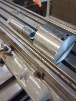
I took a shop built (ugly, from a long time ago) MT5 shank I had laying around and modified it to include threads with a lot of relief that runs up inside of the spindle when installed. Allowing the "head" to tighten up against the spindle.

I used a chunk of saved scrap 3-15/16" round bar for the head, threaded it 2" deep by 1-5/8" 12tpi.

The tool slot is 5/8 square (the only indexible tool I had that could sit inside the slot fully flush if needed.

I had planned on adding a cap over the tool slot which would also incorporate a mount for a guide shaft, similar to the cutters shown in the ATW publication. I also wanted a fine adjustment for the cutter. Impatience got the better of me however and I had to give it a try!

Chatter is no longer a problem with this setup, and Im getting better life from my inserts. The spindle did however flex very slightly under heavy, (.050 DOC) hard interrupted cutting at 100 RPM. After roughing through the bad areas I took lighter cuts of .010" DOC, kicked up the rpm to 175 and I'm getting a better finish now (not pictured) I'm sure after I can get it to a fully clean bore and raise the RPM to a proper speed it'll look nice.

I do believe if a person wants real good tolerance and precision on a Radial Drill, a guide of some sort would be necessary, but for this job, I'm getting a what I need to get the job done. I should have it wrapped up tomorrow.

Thanks to everyone for the information and suggestions! You've made my job easier and I'm a bit more educated now.

IMG_20231121_113306511_HDR.jpgIMG_20231121_151952749_HDR.jpgIMG_20231121_151600254.jpgI should have taken a before picture since the worst had been cut away by this point.
 
Are the threads pulling the Mt arbor out of the spindle or is there a draw key in that thing?
Sorry, I forgot to explain that, yes a draw wedge was firmly installed into the arbor/spindle to keep it well seated.

Thanks for reminding me to mention that, in case someone else can glean a bit of useful information out of this thread.


Back
Top