What's new
What's new

Calculate a cantilever beam?

Trboatworks

Diamond
Joined
Oct 23, 2010
Location
Maryland- USA
I have a simple load problem but am not finding a simple load calculator to check the application.

I have a 316 SS 1/2”x1-1/2”x12” bar held flat in cantilever.
Point load of 250 pounds at end of beam.

What stress is this placing at the root of the beam?
I can have flex in use, I don’t want to be near yield.

Thanks
 
Last edited:
This is a hobby project- not client work.

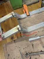
I am using the following assembly out of my scrap bin to cobble together a step for our micro camper-
The left shorter tangs are bolted under trailer deck.
This free pivots so a gusset stop arrangement to be welded on will hold step flat where red is marked, stowed is hinged up.
These tangs spread out on 24” center to hold up a 12”x32” teak step.

I figure a person stepping on one side of step out at nose is highest load so the ~250 pound number on one tang.
I just don’t want to go to the bother and have this bend the tangs over time..

E76D3816-EF70-4DB6-988B-B3636A7142FB.jpeg

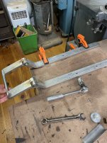
The full pieces-
Tangs are about 4” too long so will be cut back.

E26D8E05-618C-4190-AD2A-6E3B3D76FBCE.jpeg
 
Too dodgy even for this use?
Pivot bolts are 1/2”.
Lots of load on the stop gusset and pivot pins…
I guess if I was building from scratch I’d use 5/8” pins and some square tube for the tangs instead of that flat bar..
I don’t have a photo but there are fairly robust ramp gussets already welded up on the underside to reinforce those pivots.

I can just build from scratch but I’m trying to save some time by using this gear.
The basic geometry is ideal.
 
Last edited:
I have used a program called Beamboy 2.2 Its a bit confusing to use but you can set supports (including cantilever), and loads on different beams to see the loads twisting and deflection
 
Awright - if I understand correctly (short, left welded sections get holes, then bolted to underside of camper, tabs welded to bottom of short links such that tabs and short-bent section of long link butt, therefore putting pivot bolts into mostly shear load outward and downward) then I think a max of 250lbs may be OK on the step.

But, the first hole closest to the pivot in the left, short link will see (IMO) maximum bending strain, so the stop tabs you're speaking of would ideally go past that bolt hole on either side, i.e. two ~1/4" triangular plates, each about 3" - 4" on the weld leg and stop tab leg (hope this is clear).

With that setup, the weld legs of the stop tabs would reinforce the outside bolt hole, helping prevent it from bending.

What I'm not so sure of is lifetime - pivot bolt area should be ok with lubrication and not huge cycles, but the shells may oval with a lot of stepping. The bend zone on the long leg will have strain hardened a little bit, allowing more deflection without plastic deformation, but will still be subject to "unbend" if excessive loads are placed on it due to impact or whatever if the load weight's not uniformly spread between the two bars.

I'm also not clear about the wood step - is it going "up and down" along the picture axis (perpendicular to the two long links)? If it's as long as you say (32"), then there's obvious risk of stepping offset to the stainless bars, therefore putting a twist load into the assembly - this is much more complicated from a stress standpoint.
 
Its not a simple beam,its a complex structure with bends and holes .........typically ,bending austenitic stainless increases the yield strength by at least 30% ,often more .......the walkway or whatever is bolted on also increases the yield and changes the stress loadings ..........its one of those thing that you try out ,and it either works OK or needs extra stiffening.
 
Maximum stress= MC/I
M=250 lbs x 12in = 3000 in-lb
c= 1/2 plate thickness = .25 in
I= section moment of inertia= (bh**3)/12 = 1.5in*(.5in)**3/ 12= .0156in**4

Stress(max)= 3000in-lb* .25 in/.0156in**4= 48,077 lb/in**2
The stress might be ok.
Annealed 316 0.2% yield stress= 30,000 lb/in**2
Cold rolled 316 0.2% yield stress = 45,000 lb/in**2

Maximum deflection= PL**3/3EI
P=250lb
L=12in
E=29*10**6 lb/in**2
I= .0156 in**4

Maximum deflection= 250lb*12**3 in**3/ 3(29*10**6 lb/in**2)(.0156in**4) = .32in

Deflection is ok if the yield stress is not exceeded

The contact area between the stainless bars and the steel trailer frame needs to be kept dry otherwise the steel frame will become the anode in the battery formed by the dissimilar metals and the salt water trapped in the bolted joint.
 
Last edited:
I would say that it wont bend with that little weight on it, but would guess those fasteners holding it on better be decent. i think clamping load of a 1/2" bolt is good enough, just as long as the fastening to the structure is the same or better, that would be the failure point being out that far.
250lb is more then plenty, as long as its not jumping up and down on it with velocity. force = mass x velocity.
 
I would say that it wont bend with that little weight on it, but would guess those fasteners holding it on better be decent. i think clamping load of a 1/2" bolt is good enough, just as long as the fastening to the structure is the same or better, that would be the failure point being out that far.
250lb is more then plenty, as long as its not jumping up and down on it with velocity. force = mass x acceleration
:)

I bet the live load of a 200lb person stepping on it greatly exceeds 250lb, especially when he's carrying a full cooler.
 
:)

I bet the live load of a 200lb person stepping on it greatly exceeds 250lb, especially when he's carrying a full cooler.

In addition to this, your holding method is not really a cantilever beam if I understand your setup correctly. If you are only worried about the bend unbending, you just have the live load issue, which is a legitimate issue, as Robert's calculations show is marginal if your hypothetical 250 lb individual gingerly rests his weight on the end. A stomp, even from a lighter person and applied across both tines in the center, will be worse.

If your bent section rests on a gusset as described, you have also effectively produced a lever with the fulcrum at the bend, and loads at your foot and the bolted hinge. This lever arm looks like about 6:1 when considered that way, and would be even worse if the gusset stops your bent step arm from rotating at a point closer to the hinge point.

So now you've got fasteners in single shear, with 3000 in-lb of moment to counter, and an arm of 2" or so, scaling your foot weight up to 1500 lbf. This should be OK for a 1/2" bolt in single shear (10,668 psi stress) but the gusset has to counter this effective force in addition to your foot force, so it needs to be beefy.
 
Last edited:
Using the SWAG method, it will bend. Sooner or later somebody will jump on it, whether they mean to or not, and they will probably mean to jump on it. And this Merica, so they may well be over 250.

Use tubing instead.
 
Not camping YET.

I cobbled this together.
And yeah- the stop on its gussets are ~ 2” on other side of the pivot.
A perfect contraption it is..

I will post a photo in all its glory when I get it assembled.

Thanks all
 
These things dont break ,they just bend ,and you bend them back .......when I had the shop,there was bus and coach hire crowd in the next yard (Deathtraps -R-Us)........They put on a driver who weighed 300 lbs ,and he bent all the entrance steps and seat frames .......just folded sheet metal ,bent didnt break .


Back
Top