What's new
What's new

Cant Break A Chip Help!!

mhzinduction

Aluminum
Joined
Jun 7, 2012
Location
Michigan
Hey guys, I have a part that is just killing me when it comes to breaking a chip and I cant figure out what to do! (Newish to the CNC lathe world. mostly run 3 and 5 axis mills) Please be gentle with me its my first time....

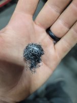
We cant seem to get the chips controlled, they're basically turning into Brillo pads inside the hole.

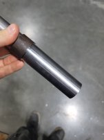
Material 4140 1.500 x 5.000 Long

Feed and Speed (SFM 400) .025 DOC .003 IPR

Doosan Puma 2600 SYII

Royal Products QG-80 Collet

F08Q-SDUPR 2-ER Sandvik Silent Boring Bar (1/2) D 10XD Length Stick out​

Insert DCMT21.51LP Mitsubishi

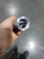
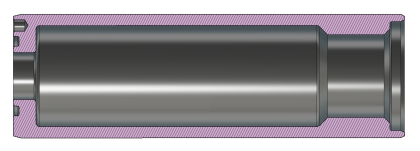
Starting bore size .850 (there is a thread at the beginning about an inch long and after that the part steps over to about 1.062

We have tried carbide boring bars and heavy metal bars 5/8 shank also. I also bought a MAQ silent boring bar with coolant thru to try and help flush the clips out.
 

Attachments

  • 20240326_170432.jpg
    20240326_170432.jpg
    1.8 MB · Views: 65
  • 20240326_170526.jpg
    20240326_170526.jpg
    1.4 MB · Views: 64
  • 20240326_170522.jpg
    20240326_170522.jpg
    1.3 MB · Views: 64
Please shine some more light on your problem.

I can't tell but it looks like the hole is blind. If it is blind, what is the bottom configuration? How deep is it? What kind of finish and tolerance is required? How many pieces?
 
Last edited:
i agree with TeachMePlease increase the feed rate you are on the very low end of the feed rate for this insert
or get a finer chip breaker to be at the feed rate you are using
 
I agree with what's been mentioned so far.

See if you can't find something like this in your Manufacturers catalog. Will help you find the proper insert/chip breaker combo to meet your conditions. Shows the expected work envelope for each insert style's chip breakers and edge geometry.

You're certainly on the low end of feed for your insert, though the last job I did on the lathe, I ended up having to slow down the feed to get 100% number 9's. So it can go either way.

Attached is how Kennametal does it.
 

Attachments

  • Kennametal turning.pdf
    609.8 KB · Views: 16
Sometimes you're gonna get a birds nest and that's all there is to it, unless your "finish pass" can be pretty rough and even then, good luck breaking a chip in duplex, lucky it's just 4140...
I have some deep/small hole parts that need to be bored, need perfect finish and tight tolerances and I have the machine go home between cuts, M0, take chips out with a little bent tig wire, go again. Sometimes that's just part of making good parts.
If you're trying to go lights out then that's a different issue.
I try to drill as close to finish size as I can as that'll get the chips out and leave just enough for a couple finish passes.
 
Can't break a chip? You need to tell us what you've tried and what hasn't worked.

Breaking a chip in 4140 shouldn't be too difficult.

There's multiple things you can try:
-sharper insert (smaller tool radius)
-higher feed
-faster surface speed
-deeper depth of cut
-different chip breaker geometry
-better coolant delivery.

Try a .008" radius insert. I think you will get better results.
 
I would agree with the others that said push it harder. I have also on occasion used a drill to break up a birds nest after roughing the bore then run a finish pass. I do not recommend it unless it is absolutely neccessary.
 
Your parameters are way out of whack.
Try like a .05 DoC, at .006 IPR, or use a bigger TNR (2 rad) and go with a .08 @ .01 IPR.

I personally would also be closer to 600-800 SFM depending on the yield of the 4140.
 
Please shine some more light on your problem.

I can't tell but it looks like the hole is blind. If it is blind, what is the bottom configuration? How deep is it? What kind of finish and tolerance is required? How many pieces?

This is the part that we're working on.

Overall depth of the pocket is 3.900". Surface finish of the ID is 125 with no tight tolerance. I only need to make 5 pieces, but this will be a production part, down the road, in excess of 10K+ a year.

1711550399102.png
 

Attachments

  • 1711545077132.png
    1711545077132.png
    295.3 KB · Views: 4
Can't break a chip? You need to tell us what you've tried and what hasn't worked.

Breaking a chip in 4140 shouldn't be too difficult.

There's multiple things you can try:
-sharper insert (smaller tool radius)
-higher feed
-faster surface speed
-deeper depth of cut
-different chip breaker geometry
-better coolant delivery.

Try a .008" radius insert. I think you will get better results.

-We have tried .031 and .015 nose radius inserts so far.
-We have adjusted the speeds between .0025-.005 ipr.
-Surface footage has been tested between 250-550 sfm.
-We have tried .02-.03 DOC.
-We have tested two chip breaker thus far.
-Coolant delivery has been thru tool as well as through a jet on the bushing depending on the bar that we use. One has thru coolant the other does not.

I will look to get some .008 radius inserts ordered up.
 
Your parameters are way out of whack.
Try like a .05 DoC, at .006 IPR, or use a bigger TNR (2 rad) and go with a .08 @ .01 IPR.

I personally would also be closer to 600-800 SFM depending on the yield of the 4140.
I would have to see how much material would remain behind the thread. We get away without having to back bore the relief behind the thread using the setup we have with the DCMT inserts.
 
Thank you for the excellent extra info. Now we have a very good picture of what you are trying to do. I see now why you are drilling such a small hole.

Maybe the undercut angle at the right is not critical, but it looks like 45*. You can't get that with a d style insert and still go to the flat bottom.

As you know, this undercut bore is not a simple walk in the park. I would peck turn this. It is amazing how little it increases the cycle time. Hopefully you have high pressure coolant and a through coolant bar. I'd use a pecking macro for absolute chip braking security. The increase in cycle time is more than paid for by less trouble, fewer scrapped parts, and hopefully no broken boring bars. If you are going to make 10K of these, you don't want to struggle with this.

In your macro, cut one or two revolutions at cutting feed, retract one revolution +.001 at maybe 3X cutting feed, reposition to the last cut at 3X cutting feed, and continue. This example is for cutting one revolution with a feed of .003 IPR. You can use a face pecking canned cycle to do this, but I like a macro so you have absolute control of the tool. I am not confidant I really know what is going on behind the scenes using a canned cycle for this.

#1 = -.003 (initial cutting depth variable)
WHILE[#1 GT -3.9]DO1
G1 Z[#1] F.003
W.004 F.012 (incremental retract)
W-.004 (incremental reposition)
#1=#1-.003 (decrement Z for next cut)
END1
G1 Z-3.9 F.003 (to insure you get to z-3.9 regardless of how the peck increment works out)

This is assuming you start cutting at Z0, which is not your case. You will have to get fancy to peck ramp in at the start, and you may need to deal with the radius at the bottom of the hole. It can all be done with macros. It may help clearing chips if you bring the entire bar clear of the hole each pass.

You'll have a controlled chip length, and the high pressure coolant will assist with clearing the hole. Be sure the chips are not blocked up at the left end through hole.
Wow! I would have to start the macro from the bottom of the rear chamfer. I would probably employ a peck cycle to clear away most of the chamfer before engaging the macro to start the undercut.

We did try the pecking cycle that the CAM outputs with no success. (Forgot to mention that in things we have tried and failed) I changed the peck depth from .001-.100 with no luck, but I will try this macro out and see if I can make it work.

Also, the hole through the center, at the back, is done on OP20 on a different machine, so that is not creating issues in and of itself. We have 460PSI coolant on this lathe but it just can't flush the chips out. Between the lenght of the chips and the backside chamfer, they cannot escape.

We have contemplated hooking up an air blast line, but I am not sure what they will do to tool life should we actual start breaking a chip.
 
This is the part that we're working on.

Overall depth of the pocket is 3.900". Surface finish of the ID is 125 with no tight tolerance. I only need to make 5 pieces, but this will be a production part, down the road, in excess of 10K+ a year.

View attachment 434318


That's gunna suck!

High Pressure through the TOOL and lower RPM to keep centrifical force to min to help flush chips would be the order of the day!

I too would day to up the feed.


---------------

I am Ox and I approve this here post!
 
Last edited:
We have contemplated hooking up an air blast line, but I am not sure what they will do to tool life should we actual start breaking a chip.
If you mean an air blast instead of 460 psi coolant, I think don't bother. The mass of the coolant at 460 psi will far outweigh air blast, even if you could get 460 psi air.

Ramping down with a macro isn't too bad. Just figure out the incremental x associated with the incremental z. For 30*, if z = .003 then x = .003 X 1.732 X 2 for diameter. or 3.464*z. Or you can just pull off straight in x and reposition.

For x retract at 30*, with Z1 being the Z destination for the desired DOC.

#1 = -.003 (initial cutting depth variable)
WHILE[#1 GT [-Z1]]DO1
G1 Z[#1] U[.003*3.464]F.003
W.004 U[-.004*3.464]F.012 (incremental retract)
W-.004 U[.004*3.464](incremental reposition)
#1=#1-.003 (decrement Z for next cut)
END1
G1 Z[-Z1], F.003 (to insure you get to Z1 regardless of how the peck increment works out)

Then proceed with the Z feed to the bottom, starting with -Z1-.003. It might be less confusing to increment x to the depth of cut and back figure z. If you use trig in the macro to figure the movement of the axis not being decremented or incremented, you'll have a macro that automatically figures the related axis when you tweak the numbers.

How are you handling the bottom of the hole? In other words, are you using a drill with a point, just driving it as deep as you can, or an indexable drill? Just curious. The flat bottom always adds a bit of excitement.
 
We did try the pecking cycle that the CAM outputs with no success. (Forgot to mention that in things we have tried and failed) I changed the peck depth from .001-.100 with no luck, but I will try this macro out and see if I can make it work.

This doesn't bode well for creating a macro., especially since you already tried a .001 peck. Is there a way to switch order of operations so you can get the bottom hole through first? Or add a drill to drill through from the first side? I feel if you had a bottom escape path you'd have a better chance.


Back
Top