What's new
What's new

Do my spindle bearings need to be replaced?

404estop

Plastic
Joined
Apr 15, 2023
Location
Raleigh, NC
Hi all, new to the forum. 👋
I am a novice/hobbyist and I am trying to assess a CAT40 spindle. I believe the angular contact bearings are shot due to the vertical play even when the locknut is applied. My logic is that there should be no vertical play when preloaded otherwise there will be chatter on parts (but that's just a guess). The bearings sound and feel fine when spinning.

Here's a video demonstrating what I described:

So do these bearings need replaced or is the spindle fine?
 
Did it have the same movement when the spindle was fully assembled within its housing and the nose cap tight? If so, you got problems that are either due to worn bearings or improper assembly. It's unlikely the balls are so grossly worn, so I'd guess there's something off in assembly.
 
What’s the background of this spindle? Did someone try to rebuild it prior to you getting the machine? Was it loose when you got the machine? If worn bearings were the cause of that much end play they would be rough and growly when spun. Since you say it’s smooth makes me think someone tried to rebuild it and did something wrong or failed to set the correct preload between the upper and lower bearing sets.
 
@Vancbiker
There was always a small amount of vertical play (inner spindle moving relative to outer) even before I opened it up.

Spindle history:
CAT40 spindle from a Hurco BMC40 machining center built in the early 90s from what I gather. I do not own the original machine. I'm messing with it for learning purposes and plan to use it for a future machine (if possible).

I purchased it about 10 years ago and it sat until now. Judging from what I've seen it's been serviced and rebalanced before. That is all I know.
 
Last edited:
So it’s very possible that someone prior to you attempted a DIY spindle rebuild without knowing what they were doing.

Setting proper preload on a quad set of bearings can be a pretty tricky process. It involves grinding the inner or outer spacer rings and/or nose piece to account for the stack up of the bearings. If a quad “universal” set of bearings with the correct preload set at the factory is available and used, you might get by with grinding both spacers to the same length.

I have also seen quad sets installed incorrectly where the pairs were not opposing each other. It is pretty common for a bearing manufacturer to mark a matched set of bearings with an etched V on the outer rings. In a quad set this V would be continuous across all 4 outer rings and that alignment maintained on assembly. There is also often a small mark on each inner ring that marks the high point of radial runout. Those marks should be aligned and maintained during assembly.

Next is grease. Often Kluber brand and a surprisingly tiny quantity.

There is a reason spindle rebuilding companies exist……
 
Thank you all :)

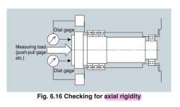
Can someone simply confirm my suspicion that there should be very little play along the axis of rotation in a spindle? I think axial rgidity this is what I'm referring to:

1681580110291.png
 
I just spent an hour looking for a free parts manual or PDF to see the spindle with no luck. Do you have a parts manual for the machine so we can look at the spindle diagram? The bearings maybe in backward. I would guess they are back to back, In your diagram they are backwards. If someone has had it apart and didn't know what he / she was doing probably screwed it up. The machine is what 30 years old? No grease in them or did you clean it out?

Also You need to install it in the head to get the proper preload as the other race have to be tight against the shoulders and cap. If it is loose when installed how bad was it? If it is 015" then the bearings were in backwards or someone put to thick a gasket on the bearing retainer cap. Preload should be set when the bearings are warm and have zero backlash. I have installed them when cold, but I've been rebuilding spindles for 50 years. So until we can see a drawing of the spindle out of a Hurco parts manual we are all guessing. From my search for a a manual it looks like Hurco has manuals and their service department will help for free.
 
Bearing orient in the drawing looks correct to me.
This might make me in conflict with Mr King whom I respect a lot. (Bad Bob.. do not want to do that.. should not speak :dopeslap:)

Here I see the pair lines cross outside for highest rigidly to side loads and the extra one in front for axial load.
There should be no slop as shown here and no need to grind anything to set the preload if precision class bearings are used.
Precision bearings now are almost all DU's, (universal mount). Back in time there were front to front or back to back grinds but those days are long gone.
Lower class or standard angular contact bearings will not work unless you want to spend a lot of time and effort hand fitting, grinding, making shims.
In a mill I'd be using M or H preload bearings depending on max speed. SG spindles like Ls.
My guess would be someone did something wrong at one time.
50-200 millionths would be okay in my book on this check with decent push pull. 10 to 20 would be really good. 200+ ... oh my. Why?
The second indicator needs to be on the housing just to make sure you are not moving the entire spindle assembly and measuring something else.

Besides good bearings, correct amount of measured filtered grease and gentle assembly it is clean, clean, clean.
Cleaning rag lint, dust...bad.
There is also bluing and scraping the bearing nut and or flange but I do no see that applying here as a problem.

Bob (pennies of some random thoughts from the peanut galley and take it as such)
 
Last edited:
Bob in most VMC mills the bearing are back to back not face to face as I see it in the drawing. In super precision grinders and gear testers I have installed bearings face to face. I have taught several classes inside Hurco in Indianapolis, so I can't imaging a milling spindle would be face to face configuration. That's what a BOOK or MANUAL would be best so we don't have to GUESS.

The you tube show bearing under the nut is back to back o the bearing at the top, but are the ones under it back to back???
 
The you tube show bearing under the nut is back to back o the bearing at the top, but are the ones under it back to back???

It could be worse than that - I didn't see any markings on the races, so it's possible that the bearings are arranged F/B (or B/F) throughout the spindle, which would allow some movement of the outer stack while free or captured.

At least, I think so - if I'm wrong someone please correct me.
 
Having been in side a few Hurcos of similar vintage (although not that specific spindle unfortunately - I even have one here, but it's currently inside a running machine...) I would absolutely expect to see alignment markers on the shells of those bearings.

That tells me someone has been in there before for sure, and the most likely explaination as others have said is that at least some of the bearings are installed in the wrong orientation.
 
Hi all, thanks for everyone's input - I love the different perspectives and experience!

Luckily 10-year past-me had the 2 extra brain cells (since depleted) required to purchase the Hurco manual and I've captured the relevant bits:

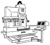
First off, a sketch of the Hurco BMC40 the spindle came from:

1681660716832.png

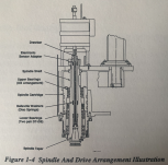
Spindle and Drive Arrangement Illustration:
1681660944822.png


1.3.3 Spindle & Drive - See Figure 1-4
The spindle is precision balanced, cartridge-type of chrome-molly alloy with #40 taper Caterpillar V-flange (standard, BT Tooling optional). The spindle shaft is supported within the cartridge by three sets (6) of ABEC-7 class angular contact bearings. This design provides reduced clearance and results in greater rigidity to allow heavier cuts with greater accuracies. Tool holder retention in the spindle is maintained by heavy disc springs which provide the clamping force to the tool holder 'pull stud' via the drawbar. The tool holder is released pneumatically during the change cycle by means of a dual-piston air cylinder supplying the necessary thrust force to the drawbar for tool release. Air 'blows' through the spindle taper when it is unclamped to aid in keeping-out foreign material during the tool change.

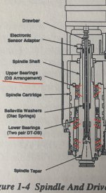
The bearing alignment lines are nearly impossible to see so this is my interpretation:

1681661611062.jpeg
 
Last edited:
That's a help, but at the resolution of the image it's a bit tough to confirm bearing orientations visually. But the text says "DB", or the "fat" outer races touch.

I'm not sure what others think, but you may have to mark the outer races, figure out how to disassemble the bearings from the spindle without damaging them (good luck), then confirm correct assembly order and orientation before reassembly. Here's an image showing common bearing pair (and 3-4 unit) setups:


This would give you a chance to check the spacers for height and parallelism, look for burrs on the spindle OD that may have prevented correct seating, etc.
 
Unfortunately Hurco doesn’t support machines of that vintage.
No point in calling them, best to go through a 3rd party.

I ran the same machine for quite a while, I seen just about every problem you could have. It went to the scrap yard running with a shot spindle.

The bearings loose their preload overtime. Those spindles need to be rebuilt by a professional.


Back
Top