So I bought a DOA ycm mill with a Fanuc OM control. Initially the control would not fire up at all but I fixed that. It had a short in the cable going to the RS232 port. Now the control is stuck in "not ready" mode. The estop has not effect. I have no power at the estop. I have limit switches apart and have no power to them for the estop string. I do get voltage through the string that feeds ot release. Does anyone know which board or where the estop string starts in the cabinet? Thanks in advance!!
How to install the app on iOS
Follow along with the video below to see how to install our site as a web app on your home screen.
Note: This feature may not be available in some browsers.
Largest Manufacturing Technology Community on the Web
Stay Connected:
You are using an out of date browser. It may not display this or other websites correctly.
You should upgrade or use an alternative browser.
You should upgrade or use an alternative browser.
Fanuc OM 'not ready" alarm
- Thread starter Dukerc51
- Start date
- Replies 31
- Views 1,875
Vancbiker
Diamond
- Joined
- Jan 5, 2014
- Location
- Vancouver, WA. USA
The machine builder determines how and what they want to include in the e-stop circuit. There are 2 places that ultimately will put the machine in e-stop. Input (Diagnostic) 21 bit 4 is the CNC input for e-stop. It will be 0 when the circuit feeding it is open. This will put the machine not ready. The servo drive(s) will usually be included in a separate e-stop circuit which opens the 100VAC input to the drive(s) also resulting in the not ready condition.
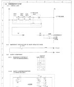
Long story short, you need to refer to your electrical schematic to see how your builder implemented their take on the e-stop circuits. If you need help with that, post images of the schematic page’s associated with e-stop and some here will be able to provide suggestions on where and how to test.
Long story short, you need to refer to your electrical schematic to see how your builder implemented their take on the e-stop circuits. If you need help with that, post images of the schematic page’s associated with e-stop and some here will be able to provide suggestions on where and how to test.
Thanks for the reply. The screen is hanging on the PMC page which I thought nothing of until I was reading an old thread you replied to stating they do that. I attached a PDF of the estop section of the electrical manual. I have the X axis limit switch cover off. No juice there. I was wondering if since I have a Not Ready alarm I am before the point where the estop circuit gets power anyways. I can check the diagnostic tomorrow morning.
Attachments
13engines
Stainless
- Joined
- Jun 30, 2015
- Location
- Saint Paul, MN
I've got a mid 90's YCM Supermax with OMC on it. If you have a panel full of cube relays in your magnetics cabinet, wiggle or re-seat the one labeled E-Stop. It's got a bunch of wires connected in back (meaning high potential for loose connections) and mine on occasion needs a little push. Like yours, it just sits there at power up with Not Ready showing and leaves you standing there thinking now what? Nothing seems to help. Then I remember the relay and all is well. You'll know when you've hit pay dirt because a couple big relays will clunk in.
Do you know which board the signal comes from at the start of the estop circuit?I've got a mid 90's YCM Supermax with OMC on it. If you have a panel full of cube relays in your magnetics cabinet, wiggle or re-seat the one labeled E-Stop. It's got a bunch of wires connected in back (meaning high potential for loose connections) and mine on occasion needs a little push. Like yours, it just sits there at power up with Not Ready showing and leaves you standing there thinking now what? Nothing seems to help. Then I remember the relay and all is well. You'll know when you've hit pay dirt because a couple big relays will clunk in.
Vancbiker
Diamond
- Joined
- Jan 5, 2014
- Location
- Vancouver, WA. USA
If you look at the diagram, you’ll see that the e-stop does not originate at a board. The circuit is probably 24VDC but you need to verify what wires 0 and 7 are. This circuit only activates the relay coil EMERGENCY. Contact(s) of this relay will almost certainly send 24VDC to input X21 bit 4 and likely break the 100VAC to the servo drive(s). That info should be on other pages of your schematic. Relay EMERGENCY should be on as long as the e-stop circuit is closed (normal condition).Do you know which board the signal comes from at the start of the estop circuit?
Does your machine have a "Standby" button?So I bought a DOA ycm mill with a Fanuc OM control. Initially the control would not fire up at all but I fixed that. It had a short in the cable going to the RS232 port. Now the control is stuck in "not ready" mode. The estop has not effect. I have no power at the estop. I have limit switches apart and have no power to them for the estop string. I do get voltage through the string that feeds ot release. Does anyone know which board or where the estop string starts in the cabinet? Thanks in advance!!
13engines
Stainless
- Joined
- Jun 30, 2015
- Location
- Saint Paul, MN
Yes 7 is 24VDC and 0 is the low side of that.
I just looked at my MAX 3 drawing and the fussy Relay coil I was talking about is the first or last (depending how you look at it) link in the E-Stop chain.
I say start wiggling relays. :-) That is if you gottem.
I just looked at my MAX 3 drawing and the fussy Relay coil I was talking about is the first or last (depending how you look at it) link in the E-Stop chain.
I say start wiggling relays. :-) That is if you gottem.
Last edited:
I will look at the schematic again. I am no pro lol. Thanks for the reply!! I do know I have no power at the first limit switch in the chain. Would the power start at the relay?If you look at the diagram, you’ll see that the e-stop does not originate at a board. The circuit is probably 24VDC but you need to verify what wires 0 and 7 are. This circuit only activates the relay coil EMERGENCY. Contact(s) of this relay will almost certainly send 24VDC to input X21 bit 4 and likely break the 100VAC to the servo drive(s). That info should be on other pages of your schematic. Relay EMERGENCY should be on as long as the e-stop circuit is closed (normal condition).
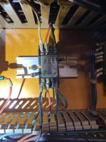
Does your relay look like this? I have a max 1 as well and the wiring doesn't match this one. I have power on 7 and 44 at the relay which doesn't make sense to me.Yes 7 is 24VDC and 0 is the low side of that.
I just looked at my MAX 3 drawing and the fussy Relay coil I was talking about is the first or last (depending how you look at it) link in the E-Stop chain.
I say start wiggling relays. :-) That is if you gottem.
44 is behind the 401 wire in the pic.
Attachments
Does your machine have a "Standby" button?
No stand by button that I can see.
13engines
Stainless
- Joined
- Jun 30, 2015
- Location
- Saint Paul, MN
I have about 20 relays on a panel. One labeled E-Stop. Whether the one in your picture is an E-Stop one is beyond me. You'd have to look in your manual.
It wouldn't be unusual to have power on more then one leg of a relay wiring setup. You might have 24vdc on one and 110AC on another. Or 24vdc on two. One for the relay coil and one to send power to the device it's meant to control.
I'm about 90% sure that 6 and 1 are 110VAC.
You might check to see if some of those wire numbers are present on any of the heavy relays in your cabinet. Especially the coil connections of such.
Vancbiker
Diamond
- Joined
- Jan 5, 2014
- Location
- Vancouver, WA. USA
The pic of the relay you posted partially matches what is shown in the schematic. Wires 400 and 401 are not shown on the diagram for the e-stop relay. In any event, this relay should be on to clear the e-stop state.
When you say you have voltage at certain points, where are you grounding to negative lead of your meter?
The relay clips being bent out of the way as shown in the pic makes me wonder what all has been messed with?
If you want to check the relay operation, you can put a jumper wire between wire 44 to wire 0 which you will probably find a few of on a terminal strip in the cabinet. This effectively bypasses all the hard OT limit switches and wiring. If the relay activates, then you will need to trace the circuit item by item until you find the bad switch or broken wire or bad connection.
Thanks! I am trying that now. First Honda connector I checked does not have 24 volts where it should. Checking the rest.The pic of the relay you posted partially matches what is shown in the schematic. Wires 400 and 401 are not shown on the diagram for the e-stop relay. In any event, this relay should be on to clear the e-stop state.
When you say you have voltage at certain points, where are you grounding to negative lead of your meter?
The relay clips being bent out of the way as shown in the pic makes me wonder what all has been messed with?
If you want to check the relay operation, you can put a jumper wire between wire 44 to wire 0 which you will probably find a few of on a terminal strip in the cabinet. This effectively bypasses all the hard OT limit switches and wiring. If the relay activates, then you will need to trace the circuit item by item until you find the bad switch or broken wire or bad connection.
Jumping 44 to 0 worked temporarily. Now I have a 101 p/s alarmThanks! I am trying that now. First Honda connector I checked does not have 24 volts where it should. Checking the rest.
Vancbiker
Diamond
- Joined
- Jan 5, 2014
- Location
- Vancouver, WA. USA
Alarm 101 means the program memory is corrupt. Turn on PWE. Then turn off control power. Press and hold the DELETE button and turn on control power. That clears the program memory.
Did that, Now I have 101 p/s alarms and 417,427, and 437 digital servo parameter alarm.Alarm 101 means the program memory is corrupt. Turn on PWE. Then turn off control power. Press and hold the DELETE button and turn on control power. That clears the program memory.
dandrummerman21
Stainless
- Joined
- Feb 5, 2008
- Location
- MI, USA
Did the machine lose parameters?
The servo settings seem gone but not the tuning ones. All other parameters are there.Did the machine lose parameters?
Similar threads
- Replies
- 17
- Views
- 576
- Replies
- 8
- Views
- 397