What's new
What's new

Haas 2006 Minimill TRP solenoid issue

Hey Tony, Thanks for weighing in!

I have not found a detailed schematic for this board yet.

I've gotten started on some of your suggestions.
I didn't actually perform the continuity test yet because I think I would need to work up some much longer leads if I'm understanding your guidance. It seems like the tests below would confirm continuity though correct??

Here are some results from ohm testing:
Test direct from solenoid: .512
same test but from leads traced back to connector (P55) at I/O board: .512
Test at solenoid again but with all connectors intact: .515

I also did some cleaning with alcohol as suggested.

I am now going to attempt the voltage checks. Is the correct procedure for this to put one probe on a ground and then use the other to probe all the various component connections?

It's good to hear there might be a less expensive repair solution if we can track down a bad component. I'd certainly want to find someone with some experience.

Thanks again!


If you have 85 volts on the solenoid it looks like leakage.

Does anyone have actual schematic of the control?

If a solid state relay there could be an internal leaky component or there could be conductive crud someplace.

You need to trace back the cable from solenoid to board.

Confirm with ohm meter.

Do 2 checks, simple continuity from end to end then measure coil resistance with cable connected and not connected.

Measure again at circuit board, the resistance connected should be same and go open not connected.

You need t be certain you have correct cable.

Now if possible follow the trace to the active component, Google the number on it to identify it.

Locate other same items on the circuit board too.

Look for any crud, some denatured alcohol and a brush and rag can work miracles.

Return all to normal and apply power.

If you found the device on Google you can see control and voltage connections.

Measure voltage on each pin when both active and not.

Do same for another same device.

If the device is bad the control voltages will be similar to the other device but the output different.

If the drive to the device is bad the voltage will be different.

Digikey likely has the device.

If the Haas fix is new board and not exchange then changing device may be worth a shot.

There are places that can replace the component, look up two way radio dealers and many have old folks like me who did component level and have the proper tools to replace if you bring the parts.

Expect to pay a minimum charge.

Sent from my SAMSUNG-SM-G930A using Tapatalk
 
The model # for the black thing w/ white block is MAC224. (another Triac??). Unfortunately it looks like I would need to remove the board again to access the pins for this component?

No markings that I can see on the C-19 (snubber cap?)

I'm hoping the solenoid is still functional. The ohm reading is identical to another nearby solenoid (.512). I have put a direct 120V lead to it and it seemed to operate correctly.

I have previously tested all the resistors on the circuit to nearby resistors and no variation there. I just need to get a bit more comfortable with the process of testing the capacitors and triacs. Thanks for all the info provided so far. I'll dive in and see what I can learn.

I'm going to owe you a nice dinner or something!!


what I cannot see on the pics is what the TO220 item is? The black thing w/ the white block around the legs. Can you get me a pic of that item? I need to see the label.
C-19 looks like a snubber cap. Might be good to look at that a wee bit too. if you see any markings...
Tips for Practical Use: Snubber Capacitors | Basic Knowledge | ROHM TECH WEB: Technical Information Site of Power Supply Design


Shotgun- A term we used in my depot days- We know the circuit is a opto-Triac and most likely that TO220 (black thing) which I need to identify. Order the Opto-triac and then the TO220 device. for a few bucks... what do you have to loose.

The buts.... a) we have yet to eliminate the solenoid itself have we? is there 84 V. w/ it unplugged? Sorry if noted above.
a') You may need a new solenoid? Like the notes above... Ohm that thing out too but I think you said you tested it above? (trying to rush to a call in a few mins).
b) the input that fires the Opt-triac is a low level signal from where? Something tells the opto to turn on at the input. Not to complicate it, and its probably not the cause but you just never know. By input path to this is from where? circuit, wires, etc. or the device itself. The manual will lay out what happens to fire the


IMO The small Resistors and Capacitors (C and R items) I am not concerned with at the moment. BUT- you can check these by comparison. We have repeating Circuit here. Compare Ohms from one circuit to the one next to it. Go 1 leg to GROUND, and them probe away from the bad to another. You can also phm PIN to PIN or node to node. TRy each side of the resistors on both circuits.


Welcome to EET 101 and your doing a super job thus far. Lots to digest from my post and Tonys's. I need to go Zoom a few calls. I sure hope 21 be a recovery year for all.
 
I have some more testing results to share. I haven't really processed this information fully to know if it tells me anything but hopefully someone else will see something obvious. I did not remove the board again yet to get voltage readings on all three prongs of the triac. I haven't quite figured out if these are different than what I'm accessing from top of board.

Voltage readings from problematic circuit

IMG_3097.jpg

Voltage readings from separate identical circuit that is switched on

IMG_3098.jpg

Voltage readings from inactive circuit

IMG_3100.jpg


Just received a call from Haas service and they had an opening in their schedule so a tech will be out this afternoon. If he tells me I need a new I/O board I'll probably hold off and investigate repairing my existing board. So all this work will not be in vain.

Thanks again for the help!
 
KK.. we're on the path. All good and from your tests and notes above.
If it were mine, I would order 2 or 3 of each of the two Semi devices and replace the opto-Triac and the Thyristor. the black unit and the white one and try it. But that's me.

On the black stick device in the TO220 package type. (important when we order from DigiKey or whereever)
After the MAC224 is there any other value? I see them in various specs that represents the specific peak repetitive off-state Voltage. Chart here. A4/4 would be my guess (200Vac?)

What is it datasheet:
Noted here: https://www.digitroncorp.com/getmed...6-2447406401c5/MAC224(A)-SERIES.aspx?ext=.pdf


what's a thyristor doing here;
Because of their fast reaction times,
regenerative action and low resistance once triggered,
thyristors are useful as power controllers and transient
overvoltage protectors, as well as simply turning devices
on and off. Thyristors are used in motor controls,

Personally- I think its as an AC circuit protection capacity.
Thyristor Protection


I need to run to a call... but to me from your pic, The white unit is suspect at first glance only. You did GREAAT on your diagramming. I'll check the dataheet a bit later. (sitting in KY.. heading home tomrrow so in car for 6 hours in am).
 
Probably getting ready to close this one down- But I saw this pic and text in a doc while working this thread. Pic for 3.18 looks to similar to what we see in the Haas pic's and I just wanted to push this up as I use this site to store my stuff for later use too.... :-) It's theory but looks like the basic sense of why and how they did this.

Pic: Triac Snubber-.jpg

from: http://rfelektronik.se/manuals/Datasheets/triac_theory_and_operations.pdf
Page 38.

WHY AND HOW TO SNUB THYRISTORS
Inductive loads (motors, solenoids, etc.) present a problem
for the power triac because the current is not in phase with
the voltage. An important fact to remember is that since a
triac can conduct current in both directions, it has only a
brief interval during which the sine wave current is passing
through zero to recover and revert to its blocking state. For
inductive loads, the phase shift between voltage and current
means that at the time the current of the power handling
triac falls below the holding current and the triac ceases to
conduct, there exists a certain voltage which must appear
across the triac. If this voltage appears too rapidly, the triac
will resume conduction and control is lost. In order to
achieve control with certain inductive loads, the rate of rise
in voltage (dv/dt) must be limited by a series RC network
placed in parallel with the power triac as shown in
Figure 3.18. The capacitor CS will limit the dv/dt across the
triac. blah blah..
 
So the Haas technician has come and gone and I'm left wondering if I've made a big mistake. Hopefully not. So he had a fresh I/O board on his truck which he swapped out and the solenoid issues disappeared. Time was up and I had to make the decision whether to pull it back out or keep it and fork over the $3300. Well my cheapskate tendencies won out and I decided to gamble on repairing the defective board myself.

One of many issues I don't understand yet is what is actually doing the switching. The low voltage side of the triac driver appear to have identical voltages on all the previous examples of active/inactive/defective circuits. What gives?

I've been tracking down the parts to order and ran into more issues.
I don't see any MAC224-A6 triacs available for purchase. I do find MAC228-6 but I haven't dug deep enough to see if that is a viable alternative.

https://www.mouser.com/ProductDetail/Littelfuse/MAC228A6TG/?qs=sK5eIuwOod6ITinfOXhWqw==


Digi-key doesn't stock the driver MOC3042 (only 3041 & 3043) but I did find on Mouser. However there are many variants that I haven't found the difference yet. Looking for the surface mount type with the bent legs.
I'm leaning towards this one.

MOC3042SVM ON Semiconductor / Fairchild | Mouser

BTW, I did speak with the Haas service fella about my plan beforehand. It is an exchange program so the core is worth another $3300. Fortunately he said as long as I don't burn a gaping hole in the board they would still take the modified board as a core in the event I fail miserably. So if this fails and I decide to purchase the new board I'll only be out an extra service call(for the 90 day warranty). Clear as mud?
 
I’ll jump in in a bit and get parts found. I worked with digikey on a replacement for the mac device.

Wow. I'm just blown away at your generosity. I guess I put that last message out in the hopes you might jump in again but wow. I've got some serious "paying it forward" to do in the future. And/or look me up if you ever find yourself in the Denver metro area.

Thank you
 
How some of us roll here. It's about learning. Folks here have saved me a few thou too!
Ps- I'm an Adjunct and have been a technical instructor and teacher for 3 decades now... and you caught me w/o many Zoom calls, a really SLOW weeks, and at a mini retreat where I get to do what I want. (no wife and no chores) LOL.

I just PM'd you a viable parts list. Post them up here when you get what you like/want and make it all work.

When putting the parts in. Have someone do it if you can find someone. OR you can, but you better practice a bit first. And you'll need the real tools. I have a post in this forum (Hass) for repairing a CPU board w/ a .27 (cent)capacitor. The gentlemen and I still chat and he's been a friend since... in this post I go over the tools and how to a component replace. See if you can use the search to find it.... Good practice ..heck , how I would need to do it. I instruct on how to use VERY sharp snips to remove the parts and what and how to solder back on. Even a suggested solder Iron I love.
Peace out
GC


Wow. I'm just blown away at your generosity. I guess I put that last message out in the hopes you might jump in again but wow. I've got some serious "paying it forward" to do in the future. And/or look me up if you ever find yourself in the Denver metro area.

Thank you
 
First off I'd like to give a huge shout out to Countryguy and Tony for all the help they provided with this issue.

I'm here to report a successful and inexpensive repair that wouldn't have happened without this terrific community. So thanks again everyone.

I ordered up the replacement components from Ebay & digikey for a total of about $50(cost of the chips I actually used was about $6 but expedited shipping and ordering some backups addded up). Also picked up a new TS100 soldering iron along with a few other soldering odds and ends. The soldering iron (again recommended by Countryguy) worked excellent and was a huge step up from the junk I've been using to date.

I spent a couple hours watching youtube soldering tutorials and then began removing and replacing components from old junk pcb boards.

Once I had built up some confidence, replacing the bad components only took a rookie like me about 20 minutes. I'm sharing my experience so hopefully others that read this and realize it is really not that difficult. At least once you have some help tracking down the bad components.

I began by flipping the board upside down to access the through hole thyristor leads. I used a combination of heat, solder wick and a solder sucker to remove as much as possible. The solder seemed to have a higher melting point than the other boards I'd been experimenting on. I then used some Chip Quik removal alloy that made it possible to heat up all three leads at the same time. This allowed me to remove the chip and white insulator intact. Perhaps not necessary but it worked well.

IMG_3067.jpg

View from front after removal.

IMG_3102.jpg

I wasn't sure which component was bad so I decided to replace both in one operation. Removing the thyristor first allowed better access to the surface mount opto-triac (MOC3042).

I then used some mini side cutters to clip the 6 leads to the opto-triac and used solder wick to clean up the pads. Soldered on the new chip. The white insulator/spacer? was glued onto the old thyristor but I was able to carefully remove without damage. I then finished up by soldering that component. Then it was just a matter of cleaning up all the flux residue with IPA. Forgot to mention this earlier but I used lots of flux in all the operations.

Not sure if anyone will every run into this same issue again but if so hopefully this writeup will help. Feel free to message me with any questions. I also have some extra components on hand I'll be happy to send along.

Finished repair

IMG_3105.jpg

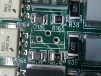
Additional pic from before repair to more clearly show the location of bad components.

IMG_3065 copy.jpg
 
Cool bit of discovery on the Circuit and why it's setup like it is. You've definitely earned your Haas badge of courage for the start of 21. LOL. Many more adventures to come for sure. so I am going on a limb to say the premature failure may well have been the conductive Graphite dust. Wondering if there are way-covers on this and have you pulled one yet to peek inside the gutter's (if it even has one?) and the motor assy's in there?). Anywho.. Congrats and have a good 21.
 
Cool bit of discovery on the Circuit and why it's setup like it is. You've definitely earned your Haas badge of courage for the start of 21. LOL. Many more adventures to come for sure. so I am going on a limb to say the premature failure may well have been the conductive Graphite dust. Wondering if there are way-covers on this and have you pulled one yet to peek inside the gutter's (if it even has one?) and the motor assy's in there?). Anywho.. Congrats and have a good 21.

Sounds reasonable regarding the graphite dust. I sure wasn't jazzed about the fact that mill had been used for that purpose. The upside is the mill looks brand new. Downside is what other problems the contamination might cause down the road. I haven't pulled the way covers yet though it has been on my to-do list. Guess I've been putting it off because I'm worried what I'll find and I need to track down what kind of sealant is needed for reassembly (RTV?)

I got caught up on a couple small machining jobs that I was behind schedule on today and the mill is performing great.

I wish you a great 2021 as well. Hope you and your son will get many interesting and profitable projects in the new year. Thanks!
 
Highroadtoolco, I'm in the same boat and shot you a PM in hopes of getting the part numbers you ordered to replace the units on the board. I'd rather not replace the entire board either.

Same situation, tool release solenoid has power as soon as the machine turns on and the diagnostics screen indicates that a tool release is not being commanded.

Thanks for the detailed thread, was a life saver once I concluded it wasn't a simple issue on my end.
 
Hey I seem to be having issues with the PM system. Let me know if you've gotten any of my messages. I do have some spare components I'd be happy to send you.

So the Haas technician has come and gone and I'm left wondering if I've made a big mistake. Hopefully not. So he had a fresh I/O board on his truck which he swapped out and the solenoid issues disappeared. Time was up and I had to make the decision whether to pull it back out or keep it and fork over the $3300. Well my cheapskate tendencies won out and I decided to gamble on repairing the defective board myself.

One of many issues I don't understand yet is what is actually doing the switching. The low voltage side of the triac driver appear to have identical voltages on all the previous examples of active/inactive/defective circuits. What gives?

I've been tracking down the parts to order and ran into more issues.
I don't see any MAC224-A6 triacs available for purchase. I do find MAC228-6 but I haven't dug deep enough to see if that is a viable alternative.

https://www.mouser.com/ProductDetail/Littelfuse/MAC228A6TG/?qs=sK5eIuwOod6ITinfOXhWqw==


Digi-key doesn't stock the driver MOC3042 (only 3041 & 3043) but I did find on Mouser. However there are many variants that I haven't found the difference yet. Looking for the surface mount type with the bent legs.
I'm leaning towards this one.

MOC3042SVM ON Semiconductor / Fairchild | Mouser

BTW, I did speak with the Haas service fella about my plan beforehand. It is an exchange program so the core is worth another $3300. Fortunately he said as long as I don't burn a gaping hole in the board they would still take the modified board as a core in the event I fail miserably. So if this fails and I decide to purchase the new board I'll only be out an extra service call(for the 90 day warranty). Clear as mud?
So what was the replacement parts you used for the MAC224-A6 ?


Back
Top