Many thanks for everyones help and suggestions.
The crank finally graduated from its weight watchers class on 3rd of October. Jody claimed to be very pleased and quite happy to pay £350 for the job.
Standard Crankshaft
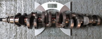
Lightened by 2.9 kg to be a close copy of works racing crankshaft.
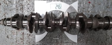
Engine it's going in is even more highly tuned than the works BMW engines were with a useful rev range of barely 1,000 rpm. Very hard work to keep in the rev range with a standard crank compared to when using the old, now bent, works crank.
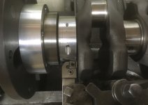
I used an aluminium ring to set the end of cut position of the tool with respect to the lightening curve template. Inserts were Sandvik CNMG 12 04 08-23 in left and right hand holders. Despite some impressive red hot hard spots two inserts managed the whole job with my wartime built Pratt & Whitney 12 x 30 B purring along at 232 rpm, 1.8 thou feed per rev and 25 thou cut taking about 1 1/4 hours for one side of each balance weight web.
Things got a bit crowded at the tailstock end when doing the left hand side of a balance weight web.
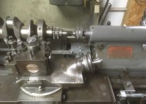
Touch more space doing the other side
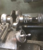
Complete crank partway through the job with no tool fitted to show the template for the lightening curve and its follower. The alloy adapter piece holding the drive end of the crank dead centre to the modified P&W catch plate is just peeking into shot.
The curve was cut by setting the lathe in power crossfeed mode so the 1/4 pin running along the template shifted the saddle as required to make the curve once the feed had gotten past then plain straight bit. The follower pin is held in a nominal 1" square bar bolted across the end of the short cross-slide. Suitably received to clear the sides.
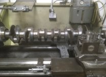
Getting the template and follower pin assembly to behave was much, much harder than I expected. Classic case of finding out the difference between knowing how a job could be done and what is needed to actually do it.
First try at the template was to trace the curve off the bent works crank using a blunted insert as the probe and a sharp point in the hole where the follower pin would eventually go. Less than successful.
Second try was to plot out the scribed line and cut curve to match. Lots of work for little reward.
Third try reworked the plotted curves to use arcs generated by a pair of hole cutters with hand filed transition curves. Which wasn't close enough.
Fourth try was to use a dial gauge on a bed mount to measure the error between the first template followed by a 1/4" pin relative to the shape of the works modified web when probed with a blunt insert. Around 150 co-ordinate cuts per side using the Bridgeport in manual "welcome to the CNC experience" mode got me a template that was close but not quite right. Repeating the process got me one that was very close to the works crank but proved to have some parts of the curve too steep for the P&W to follow in cross feed mode. Analysing the co-ordinates let me produce a new set with less slope in the offending areas. Which is what I used.
Was disappointed do discover than the follower find didn't rotate in its hole despite adequate clearance and plenty of oil. Maybe a needle roller bearing would be better.
Incidental bits included making a carrier for the template, a bed mounted dial gauge carrier and a bed mounted micrometer carrier. The latter two being things I ought to have made ages ago.
Took way longer than expected but at least the crank was in my hands for rather less time than it sat of the shelf of the professional tuning shop who had promised to do it on their CNC lathe. Fortnight turnaround promised. Finding the crank still on their shelf 5 months later did not impress Jody.
Fortunately for me Jody understood that I had all sorts of other commitments and would need some time to work out how to do the job so he wasn't worried about the further delays. Translation. He was getting desperate. Now I know what to do and have the gubbins I could turn one round in a week if pressed. Don't understand why the man with the CNC couldn't be bothered as it would have been trivial job for him.
Clive


