What's new
What's new

Motor pulley taper - is this worth fixing?

ballen

Diamond
Joined
Sep 25, 2011
Location
Garbsen, Germany
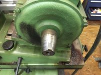
A number of you know about my Studer RHU-450 cylindrical grinder, which I bought a number of years ago and fixed up.

Recently I got a bunch of parts that fit it, including different sized motor pulleys. If the grinding wheel wears, you put on a larger motor pulley to get higher rpm on the wheel. The pulleys are very nicely made, with a ground taper inside and a relieved section in between the large and small diameter parts. Here is the current 62mm motor pulley:

IMG_9943.JPG

When I took off this pulley, I discovered that a some point in the past the motor got swapped. Whoever fixed it produced the following hack:

IMG_9935.JPGIMG_9941.JPG

They also slotted the pulley to match:

IMG_9940.JPG

The path of shortest resistance is to just slot the three new pulleys in the same way. But the current 62mm pulley has about 0.15mm = 0.006" of runout, all coming from that crappy taper bit, so it's temping to do a better repair. How would you fix this?

Cheers,
Bruce
 

Attachments

  • IMG_9938.JPG
    IMG_9938.JPG
    2 MB · Views: 5
There's not a lot of engagement of that key with the pulley, I'm guessing it is more there to keep the tapered shim from slipping. I'd just remove that key and Loctite the shim in place (assuming it is well made, replace it otherwise) and leave the other pulleys unmodified.
 
Hi Bruce,

Earlier today I removed my main OD spindle motor pulley.
Ostensibly it's configured the same as your modified non OEM set-up, however the motor spindle is 18mm (measured from what's just showing with the keyed taper adaptor still in place).
I'm reluctant to remove this taper adaptor as you could appreciate.
Here's what I'd do.
Dismantle the motor, removing the armature, machine and cylindrical grind the nose of the spindle down to 18mm and woodruff key it.
Manufacture another tapered arbor to suit that new motor spindle and your existing non modified pulley tapers.
In the absence of being able to buy another non modified pulley to complete your set, I'd machine one from scratch, with shoulders if you couldn't produce it with an OEM style crown.
The thing is you need a cylindrical grinder for a portion of this process...
Hope this helps in some way?

IMG_8668.jpgIMG_8669.jpg

Regards,
Jesse
 
Hi Jesse,

Thanks so much for taking off the pulley from your machine: I was hoping you would show me the OEM solution.

You are right, the motor that has been fitted to mine (nameplate below) has a 24mm shaft not an 18mm one. Your solution is a good one, since it would get me back to the OEM configuration.

That pulley taper needs to be tight enough to resist the torque of a 3HP motor running at 3000 rpm, which is about 5 foot pounds. Probably the reason that the small end of the pulley is so chewed up is that it was slipping.

Main question I have is this. When you took off the pulley (by the way, nice puller!!) why is it that the pulley came off, and not the adaptor? What retains the taper adaptor on the motor shaft?

IMG_9936.JPG

Cheers,
Bruce
 
No worries Bruce,
Happy to supply some info in your direction...for a change! ; )
I'd has-at-a-guess that the tapered adaptor, that while being keyed is also cryogenically installed onto an interference fit and then finish ground in situ with the motor casing bearing faceplate also installed and 'managed' within that finishing process.
The taper obviously releases instantaneously with an appropriate puller.
Possibly also some retaining compound (Loctite 609) used also on assembly?
 
I can appreciate wanting to get equipment back into good condition, but longer term wouldn't it make sense to use electronic variable frequency for speed changes on the motor rather than pulley changes?

You might be there already and the extra pulley purchase simply precipitated inspection of the previous installation so ignore if appropriate.
 
Assuming that adapter is solid-doesnt move, I would do the following. Take the shaft out of the motor, cut the exposed part of the key down, grind the od taper so the runout is .0001 or so (assuming you have room-if not grind-plate-grind), rebuild with new bearings and go. No key is needed in this taper lock style, many motors/spindles dont have one.
 
I can appreciate wanting to get equipment back into good condition, but longer term wouldn't it make sense to use electronic variable frequency for speed changes on the motor rather than pulley changes?
There is a lot of sense in this. The pulley is sized for a motor running on 50 Hz power at 2830 rpm. If the motor can be run without issues at 60 Hz, that increases the rotation speed to 3400 rpm, corresponding to a wheel diameter reduction from the nominal 300mm to 250mm. The only thing that gives me second thoughts is that the motor is only rated for 50Hz and has class E rather than class F insulation. The other point is that swapping pulleys does not require purchasing, configuring and then installing a VFD and control panel into a 65 year old machine that wasn't designed for it.

Any opinion on how likely I am to damage the motor running it at 60 Hz? What about 70 or 80? If I want to use the 200mm wheel mounted on the right hand side of the spindle, that means 75Hz.

See post #4 for the motor plate. Leroy-Somers is no help, they say "this motor is too old, we have no info about it or parts for it".
 
The vfd plan does not address the runout issue, which will only get worse with more rpm.

But to go vfd it’s probably easier/better/cheaper to buy a motor/drive combo designed to work together. That would solve both issues, assuming such a beast exists or can be modified for this application
 
The creeping investment problem. So a VFD might be a usable and affordable option. But while we're talking about options, one might as well replace the motor too with a modern, VFD rated rated one and you get new bearing and new insulation in the bargain. But why stop there? With a larger pulley you could raise the wheel rpm and do internal grinding with a 100mm wheel while also getting sufficient torque at a low frequency for the larger wheels. And while one is doing that ......

Where does it all end? The mind boggles, the head hurts.

Perhaps I need to apologize for tossing that wrench in there in the first place. I've got no particular expertise on VFD drives though my former employer used them up to several hundred horsepower. Maybe a good motor shop could give you advice on this motor based on its design.
 
The issues with running motors with a VFD at frequencies outside of their design limits are heat (which can be monitored) and voltage that exceeds the insulation of the windings limits. When a motor is designed for a narrow 50-60Hz frequency range they can optimize everything to run efficiently at those speeds. When you slow it down, there will need to be more current to maintain the torque and saturation/eddy currents cause loss of efficiency which all create heat, coupled with the integrated fan running slower and being designed to work at a specific RPM that compounds the problem. But for small deviations from the normal speed, and the lighter duty of a home shop it may not be an issue at all. External airflow assistance with a powered fan is also an option.

As far as the excessive voltage, insulation usually has a good safety margin, but it's there for a reason. Arcing the windings is going to destroy the motor. But a high quality VFD (I use Mitsubishi FR-E's) has a lot of settings that limit current and voltage and can be pretty gentle if set up correctly. None of my motors are rated for VFD use, and so far I've not had any issues, they run quiet and cool, but again 'home shop' so you need to factor in the usage and every motor is different.

But if you are prepared to buy a new motor anyway, there's nothing wrong with trying the VFD with the existing motor. Test it carefully, getting a baseline running it at the designed frequencies. Then slow it down little by little to see how much thermal increase you get. Then do the same for higher speeds. Honestly 40-70Hz may be all the adjustment you need with the right pulley, and that's not pushing the motor wildly out of spec.
 
Older motors tend to have good insulation, although of an older type. They often will stand higher voltage than newer machine-assembled motors. I've seen a lot of old motors pass a corona voltage test where newer ones failed.

Running slow does tend to have poor cooling, so external fans, or avoiding speeds below about 2/3 of nominal are advisable. A 50/60 Hz motor will have a more effective fan in many cases than a 60 Hz only unit.

I have never seen an older motor fail on a VFD other than a couple that were abused pretty badly.
 
Perhaps I need to apologize for tossing that wrench in there in the first place. I've got no particular expertise on VFD drives though my former employer used them up to several hundred horsepower.
No apologies needed, I have two VFDs in my shop, one on my lathe (TECO VFD, Reliance motor, 2HP) and the second is on my woodworking dust collector (TECO VFD, Baldor motor, 3HP). Adding another VFD and a suitable motor would make sense for this machine, so I appreciate your raising that option. Just not yet sure that I will go this route.
 
Just to add, the soft start and braking features (safety) are often worth the price of a VFD alone. Also, I meant to ask if you actually measured the pulley that was on there? The way that the lettering is cut off, it looks like they might have turned down the diameter quite a bit.
 
What if you fill the keyway with a bolted in key (perhaps even weld it up)
Grind the shaft if need be so you have no runout and no key anymore
Be sure to have a shoulder on that motorshaft
Make a split tapered sleeve that rests against the shoulder Harden and grind it even perhaps
Push the wheels on the taper with the centerbolt (I like to use a stud in such situation to keep the ID thread in good order)
Make a puller which you bolt onto the wheels with 2 bolts to take off the wheels
Peter
 
Just to add, the soft start and braking features (safety) are often worth the price of a VFD alone. Also, I meant to ask if you actually measured the pulley that was on there? The way that the lettering is cut off, it looks like they might have turned down the diameter quite a bit.
Factory diameter was 65mm, measured diameter 62.5mm. It is worn, possibly from use or possibly from the belt slipping on startup.
 
What if you fill the keyway with a bolted in key (perhaps even weld it up)
Grind the shaft if need be so you have no runout and no key anymore
Be sure to have a shoulder on that motorshaft
Make a split tapered sleeve that rests against the shoulder Harden and grind it even perhaps
Push the wheels on the taper with the centerbolt (I like to use a stud in such situation to keep the ID thread in good order)
Make a puller which you bolt onto the wheels with 2 bolts to take off the wheels
Peter
Hi Peter, I like this approach, especially the split tapered sleeve, which I can make on the grinder before I rehape the motor shaft. I had not thought of it. The alternative would be to attached the tapered sleeve with loctite. That works fine until one has to change the motor bearings, then it must be removed with heat, being careful not to damage the motor.
 
If you go this route I would sugjest to make the sleeve flusch with the end of the shaft or protruded and also protruding the wheel
That way you can make the puller seat against the sleeve so does not pull off the sleeve first

Peter
 
If you go this route I would sugjest to make the sleeve flusch with the end of the shaft or protruded and also protruding the wheel
That way you can make the puller seat against the sleeve so does not pull off the sleeve first.
Yes, you are right! This was a point that was worrying me, this is an easy solution :)


Back
Top