What's new
What's new

Removal of FP2NC Z Axis Gibs

rimcanyon

Diamond
Joined
Sep 28, 2002
Location
Salinas, CA USA
Now that I have machining done for my two main projects, its a good time to address a few problems on the FP2NC. First I would like to remove and inspect the Z-Axis gibs. Objective is to correct the table sag.

Some questions:

I was thinking of using some diagonal blocking to force the saddle up against the column while the gibs are off and while they are being re-fitted.

The enclosure back panels need to be slid out of the way, but I think the rest of the enclosure can remain.

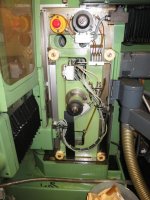
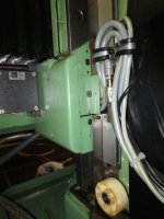
How does the operator's side gib come out? The gib bottom is hidden behind a green cover. I've removed the front screws holding on the cover, but it is still held in place. It looks like the assembly with the Z axis optical scale reader head can be loosened then slid out of the way (after detaching the grey wiring bundles, and probably some additional disassembly, hopefully not involving removing oil lines). If so, then I think the knee should be raised almost to the top, so the reader head assembly can be slid down, but I'm open to suggestions.

When the gibs are refitted, is there any means of adjustment provided, or grind to fit? Is turcite a good option for the gib sliding surface?

-Dave
 

Attachments

  • IMG_2301.jpg
    IMG_2301.jpg
    92.7 KB · Views: 366
  • IMG_2303.jpg
    IMG_2303.jpg
    85 KB · Views: 339
Not hearing any comments to the contrary, I went ahead and pulled it all apart. Pretty much everything has to come off, including the X axis stops. Some photos follow.


IMG_2304.jpg

IMG_2305.jpg

IMG_2310.jpg

IMG_2313.jpg

IMG_2314.jpg

The ways and gib are in really good condition. Measuring the gib with a mic, the turcite side shows almost no differential wear, i.e. the thickness is very uniform with about .0001" of variation. The surface of the gib that bolts to the apron was not ground parallel to the turcite side, which is interesting; even more interesting is that the bottom is ground lower by .0003". The turcite side is thicker than the side that bolts to the apron by about .0005" at the top. The screws holding the gib to the column were not very tight, easily loosened with an allen wrench.

At this point, I don't think the table sag has much to do with the Z axis gibs, so I want to look at the X axis top gib. Before I button it back up I plan to make a clamp to pull the saddle tight against the column and then measure the difference in height btw. the way surface and the back of the saddle, where the gib attaches.
 
Another thing I found when I had the Z axis scale out is that the seals are totally shot. I've heard about a company in L.A. that will rebuild all three scales for $1k, but that seems expensive just to replace the seals. Is there a source for the seal material?

IMG_2307.jpgIMG_2308.jpg
 
Deckel Doctor has the seal material at a reasonable price. I can't remember ATM what I paid, but it seemed cheap.
 
Hi Dave,

Another thing I found when I had the Z axis scale out is that the seals are totally shot. I've heard about a company in L.A. that will rebuild all three scales for $1k, but that seems expensive just to replace the seals. Is there a source for the seal material?

In Germany Singer sells the seal material by the meter, or you can buy it from a Heidenhain dealer in the USA. If the scale is an LS803 or similar, with the green or the clear sealing lips that can slide out, then ID# 222282-03 is the replacement sealing lip, USA list $ 37.13 per meter. If the seals are crimped in, then you need to regrind some cheap nippers to open the crimp, photo attached.

IMG_2633.jpg

Cheers,
Bruce
 
The ways and gib are in really good condition. Measuring the gib with a mic, the turcite side shows almost no differential wear, i.e. the thickness is very uniform with about .0001" of variation. The surface of the gib that bolts to the apron was not ground parallel to the turcite side, which is interesting; even more interesting is that the bottom is ground lower by .0003". The turcite side is thicker than the side that bolts to the apron by about .0005" at the top. The screws holding the gib to the column were not very tight, easily loosened with an allen wrench.


That machine looks to have been reworked at some point based on the scraping i see on the back of the box ways.....Factory finish is ground here.

Height of the Turcite relative to the steel bolt up face is a function of how the box fits up to the vertical slide...If the way face of the vertical slide has been scraped
and reduced in height the turcite on the face of the plate gib would need to compensate...

The difference in height top to bottom could reflect a difference between the face of the vertical slide way faces and the plate bolt up surface on the vertical slide....
When i did my FP3NC i was careful to scrape the slide bolt up face to match the way faces that bear against the box face so that fitting the plate
gib would be easier....Did mine by first grinding the back face flat on a good surface grinder. This was accomplished by fitting blocks that were
held to the bolt up face through the bolt holes having contact only on the bolt up face (not the Turcite) . With the gib plate supported on these riser blocks the back was ground flat.
Then all turned over risers removed and the Turcite and bolt up face made flat to each other....true with the back. Then some additional cuts taken on just the steel bolt up face to give the Turcite
the height needed above the steel mounting face.....

I gave the Turcite about .001" of crush over the measured height (slide bolt up face to the back face of the box way)
Then i carefully scraped the Turcite to get a very light pattern when tightened to the vertical slide....Tested the slide movement by using a chain hoist on the slide before refitting the "Z" screw....
Made mine move smoothly and fall by gravity with both plates fitted and no "X" slide....


Cheers Ross
 
I had A Tech Authority, Inc in Chino,ca rebuild two scales on my FP2NC. They replaced the seals, cleaned and checked the output on one, and replaced the photo sensor, seals on the other. They did tell me that parts are getting hard to come by for these old scales, most internal parts are now from scrapped units.
 
That machine looks to have been reworked at some point based on the scraping i see on the back of the box ways.....Factory finish is ground here.

The difference in height top to bottom could reflect a difference between the face of the vertical slide way faces and the plate bolt up surface on the vertical slide....
When i did my FP3NC i was careful to scrape the slide bolt up face to match the way faces that bear against the box face so that fitting the plate
gib would be easier....Did mine by first grinding the back face flat on a good surface grinder. This was accomplished by fitting blocks that were
held to the bolt up face through the bolt holes having contact only on the bolt up face (not the Turcite) . With the gib plate supported on these riser blocks the back was ground flat.
Then all turned over risers removed and the Turcite and bolt up face made flat to each other....true with the back. Then some additional cuts taken on just the steel bolt up face to give the Turcite
the height needed above the steel mounting face.....

I gave the Turcite about .001" of crush over the measured height (slide bolt up face to the back face of the box way)
Then i carefully scraped the Turcite to get a very light pattern when tightened to the vertical slide....Tested the slide movement by using a chain hoist on the slide before refitting the "Z" screw....
Made mine move smoothly and fall by gravity with both plates fitted and no "X" slide....


Cheers Ross

Ross,

it appears that my fp2nc's Z-axis has nowhere near the crush you built into the fp3nc. Which would account for part of the sag. I haven't measured the offset between the saddle's bolt-up face and the back of the box way, but I held a knife-edge straight-edge up and checked for daylight, and there appears to be .0005" at least (the back of the box way being lower). So it appears that there is zero crush. I will have more to say after I rig up some clamps to pull the saddle tight against the box ways.

I have the table supported by the overhead hoist currently, but everything is still attached, so I don't plan to replicate the test you used to make sure the table drops under gravity with the screw removed. I think what I will do is use the Z axis hand crank to try and get the same information. I have never tried to use the hand crank when the Dialog control was powered down - does that work? I've adjusted manual mill z axis gibs that way.

-Dave
 
Hi Dave,

In Germany Singer sells the seal material by the meter, or you can buy it from a Heidenhain dealer in the USA. If the scale is an LS803 or similar, with the green or the clear sealing lips that can slide out, then ID# 222282-03 is the replacement sealing lip, USA list $ 37.13 per meter. If the seals are crimped in, then you need to regrind some cheap nippers to open the crimp, photo attached.

Cheers,
Bruce
Hi Bruce, thanks for that information. I like the tool you made to expand the crimped portion of the scale. I need to order some parts from Herr Singer anyway, so I will contact him.

Deckel Doctor has the seal material at a reasonable price. I can't remember ATM what I paid, but it seemed cheap.

Mud, thanks for the info. I haven't had a lot of success getting Deckel Doctor to respond to email, so I will try Singer first.

-Dave
 
Mud, thanks for the info. I haven't had a lot of success getting Deckel Doctor to respond to email, so I will try Singer first.

-Dave

Just keep calling his number until he answers. If he's home, he'll answer. Don't leave messages, that doesn't work.
 
There is one other issue I should probably address when I have the scales off. The machine cannot find the reference point in mode 3. I don't recall which axis has the problem for sure, but I think it is X. I'm wondering if the solution could be something simple, like cleaning the glass scale, or possibly the glass scale is reversed and the reference is at the other end ... or are there any other possible explanations? i.e. perhaps the scale was replaced at some point and the replacement was not the correct type. Is the reference point visible when inspecting the scale carefully, and if so, what does it look like?

-Dave
 
Dave:
Don't think i ended up with any crush on the plate gibs....Started with them tight but scraped back to very light contact...
Gotta have some room for oil i think....That 220 takes a bit of space.

Some clearance and forward tip would be fine i think as long as the contact was constant top to bottom when loaded with the table and all....


The reference point is a individual file marker and read i believe by different photo cells..Believe tehe output of pind 7,& 8 are the reference mark outputs for an LS903 scale...Cleaning might get it back, but i think it is more likely an alignment thing and needs to be adjusted by someone who knows what their looking at....

Cheers Ross
 
Hi Dave,

Is the reference point visible when inspecting the scale carefully, and if so, what does it look like?

I can only speak with authority about LS803 and LS803D scales, which I have worked on and restored. By default the scales have reference marks 35mm from one or both ends. The reference marks are sensed by a pair of back-to-back photocells, which read a track near the edge of the glass scale. If you remove the sealing lips, then you can easily see the track with a jewelers loupe and a good light. On the scales that I have examined, the reference marks are every 50mm along the track, BUT they are covered with epoxy paint except for the two marks at the ends. So for example a 220mm scale has reference marks at 35mm, 85mm, 135mm, 185mm but the ones at 85mm and 135mm are masked off with paint. Bottom line, study this with a bright light and loupe and you can verify the existence of the marks on the scale. If the marks are present then it could also be failed photocells (unlikely) or a broken wire in the cabling from the reference mark or a failure in the display unit. You can test for this by swapping scales and seeing if the ref mark function returns.

Cheers,
Bruce
 
Dave:
Don't think i ended up with any crush on the plate gibs....Started with them tight but scraped back to very light contact...
Gotta have some room for oil i think....That 220 takes a bit of space.

Some clearance and forward tip would be fine i think as long as the contact was constant top to bottom when loaded with the table and all....


The reference point is a individual file marker and read i believe by different photo cells..Believe tehe output of pind 7,& 8 are the reference mark outputs for an LS903 scale...Cleaning might get it back, but i think it is more likely an alignment thing and needs to be adjusted by someone who knows what their looking at....

Cheers Ross

Check. I misread your original post and thought you assembled it with crush. Zero clearance it is. Regarding the scales, I plan to replace the rubber seals and clean the glass scales, and do some testing to see if the problem follows the scale. If it turns out I have one problematic scale I will send it to the experts for repair.

-Dave
 
Hi Dave,

I can only speak with authority about LS803 and LS803D scales, which I have worked on and restored. By default the scales have reference marks 35mm from one or both ends. The reference marks are sensed by a pair of back-to-back photocells, which read a track near the edge of the glass scale. If you remove the sealing lips, then you can easily see the track with a jewelers loupe and a good light. On the scales that I have examined, the reference marks are every 50mm along the track, BUT they are covered with epoxy paint except for the two marks at the ends. So for example a 220mm scale has reference marks at 35mm, 85mm, 135mm, 185mm but the ones at 85mm and 135mm are masked off with paint. Bottom line, study this with a bright light and loupe and you can verify the existence of the marks on the scale. If the marks are present then it could also be failed photocells (unlikely) or a broken wire in the cabling from the reference mark or a failure in the display unit. You can test for this by swapping scales and seeing if the ref mark function returns.

Cheers,
Bruce

Bruce, thanks for sharing that info. I will clean the scales and look for reference marks. When you rebuilt your scales, did you do any adjustment of the reader head photocells?

-Dave
 
Dave:
Don't think i ended up with any crush on the plate gibs....Started with them tight but scraped back to very light contact...
Gotta have some room for oil i think....That 220 takes a bit of space.

Some clearance and forward tip would be fine i think as long as the contact was constant top to bottom when loaded with the table and all....

I found the Deckel spec for my FP7NC is .0004" FOR 220 way lube. It was factory set at .0002" for 68 way lube then increased to .0004" and 220 because of scoring problems in the field.

I confirmed this in a service manual from Monarch for a VMC with Turcite lined ways - they call for .0004" measured with a dial indicator in a machine that uses 220 way lube.

Mud, that's interesting. I measured the offset of the saddle bolt surface from the rear of the box ways, and it is .0006" at top, .0009" at bottom. i.e. clearance is .0001", measured statically. I'll put it back together as it is and look for the source of the table sag elsewhere.

-Dave
 
Hi Dave,

When you rebuilt your scales, did you do any adjustment of the reader head photocells?

When I rebuilt the LS803 scales on my FP2, all that was needed was a careful cleaning and new lips. The lips had deteriorated to the point where there was nothing left, and they were full of sawdust and goop. Some details are here.

I then bought some non-functional LS803 scales from Ebay and fixed them up so that I would have a set of spares. One of those scales had a dead bulb, so I replaced that with an infra-red LED and then had to adjust the photocells. For this purpose, I built a three-channel trans-impedance amplifier, needed to convert the 11 microamp currents into voltages.

There are five screws to adjust. They don't shift any mechanical alignments, instead they control the amount of light falling from the bulb/collimator assembly onto the photocells. Two screws adjust the light for the X+ and X- cells, two screws adjust the light for the Y+ and Y- cells. Roughly speaking, these four screws adjust the radius of the Lisajous figure in each of the four quadrants. The fifth screw adjusts the light level for the reference cells.

At some point I need to sit down and write up a good description of how this works, but at the moment I just do not have the time.

Here is the amplifier, and the Lisajous figure.

IMG_3783.jpg

The amplifier is three channels of transimpedance (X, Y, reference mark) with a single-rail power supply for simplicity but with a zero reference that floats halfway between the rails. The big potentionmeter is for adjusting the bulb/LED current.

IMG_3779.jpg

The scope is in X/Y mode; the Lisajous figure shows the pattern of X/Y (0 and 90 degree phase) as the scale is scanned. As one scans in one direction, the trace rotates CW and scanning in the other direction makes the trace rotate CCW. Each rotation on the LS803 corresponds to 40 microns of motion. The scope scale is 1 division = 5 microamps, so the scale is about 30 microamps peak-to-peak.

Cheers,
Bruce
 
Last edited:
Bruce:
Any chance you might post the circuit print /sketch for that 3 channel amp, and a part number for the LED that you selected?

Nice work by the way.

Cheers Ross
 
There are five screws to adjust. They don't shift any mechanical alignments, instead they control the amount of light falling from the bulb/collimator assembly onto the photocells. Two screws adjust the light for the X+ and X- cells, two screws adjust the light for the Y+ and Y- cells. Roughly speaking, these four screws adjust the radius of the Lisajous figure in each of the four quadrants. The fifth screw adjusts the light level for the reference cells.

Bruce, I learned a lot from your post and from the one you linked to, thanks for all the details. I'm still not clear about how the reference marks are read. Maybe it will be more clear after I look at the scales with a magnifier.

-Dave


Back
Top