What's new
What's new

Monarch Series 61, Rebuilding for Improvement

Sorting THIS.. is crucial.

"Job ONE".. is to vet the best possible points of reference.

Even if you have to create them.

No stable and accurate reference as planning and starting point for guidance?

No favourable outcome.

No matter HOW hard you work.

Not just on machine tools, BTW.. Life in general, actually.

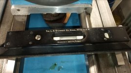
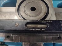
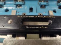
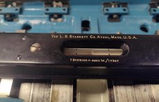
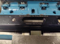
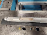
Good Point. Also part of my plan to reference off the good sections of bed. In the case of using my level, the head stock is in my way from fully reaching clean, untouched way surface. If/when I grind ways, headstock will be off again.

My intention in that regard is to reference, and be able to repeat. Where I start at un-wore section at headstock, at zero. Traverse bed to other end and achieve zero at TS end. And back again. . .

If I can do this, then I will traverse and grind, bringing my untouched, and high sections of bed down to reach the bottom of wear. Where I can hopefully read zero the entire length when finished.

I'm still a bit away from pulling that trigger, but its something I've been prepping for quite a while. At a minimum I'd like to do inner vee way and outer flat. If it goes very well I'd like to do inner flat as well.
 
You are leveling the bed on the top of the V ways. It may give you false readings because the top is narrow and it may get damaged or wear faster than the sides. It may make more sense to use the carriage top to level the bed or construct a jig that rides on the sides of both V ways. Another option is to use the flats of the bed assuming they are machined at the same height, just plop the level on the top of some 123 blocks. One more thought. If your 199 is scraped the traditional way, with a slight hollow to the center, moving it sideways may also give you a slight error. That bubble is a fickle friend it can move a division or two for many reasons. That is a beauty of a lathe :)

Apologies, it may look like I'm sitting on top of vee ways, but I'm not. The pics I posted don't show it well, but I'm leveling front to rear using the flat ways.

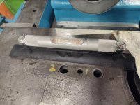
A pic from the last time I leveled shows the set up I'm using to clear the vee:

342.jpg

In one of the pics you quoted, you can just see a part of my parallel to the bottom right side of pic.

The parallels are something I made from 3/4" or 1" hss lathe tools. I put them both together on my surface grinder, at the same time. I ground both opposing surfaces, with the tools side by side on the mag chuck. The results of that are pretty decent.

Also, part of my checking ritual is to rotate the level 180, and check the same spot. I also swap the two parallels in checking the same spot. It gets tedious, but I avoid tool bias, and usually find if I picked up a small piece of dirt or something throwing me off.
 
Monarch saddles "bridge" ..... a longer span than average.

You do not NECESSARILY need to go "all the way to the bottom of wear" at all.

"Perfect" is often the enemy of "USEFUL, sooner and more affordably."

If I were to do but ONE surface on a 10EE, inner face of major front-most Vee would be it. Inner is where the wear is, outer not so much.

Underside of the carriage is FAR more worn, but that comes out in the wash with the raising of it back to OEM height.

I don''t have to care about the TS ways.
I can adjust the TS tip.

I'm going to say I totally agree with this. And in fact my primary goal is the inner vee. Also I'm pretty much on board with 75% gain, and 25% cost philosophy.

Why I may deviate from that: I suspect the grand majority of my time will set up and prep for the tram to make this happen. With the actual grinding taking less time. If it can work, and if results are good, then the time expenditure to clean up the two flats will be marginal.

I do think I might get OCD or overthink some areas. On this I feel a little more flexible, as I no doubt expect some "gray areas". But my real goal is "improved", not perfection.
 
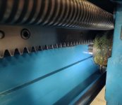
My pinion gear is pretty decent. It does have mild wear on teeth, but no wear through the hardness, and the teeth are not distorted. In the pic it appears I picked up some dirt from the bed rack, I'll be re-cleaning that. I also didn't feel the need to paint every dark hidden corner of the lathe, the gremlins who might view those areas may not approve, but they'll have to deal with it. :D

My first step is getting a rough idea of numbers needed to raise the carriage to acceptable heights. Moving the carriage to tail stock end and checking the backlash, it is indeed excessive.

404.jpg

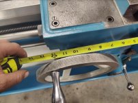
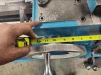
Also I don't particularly like the way the hand wheel can bang back and forth in between that backlash. The actual amount of travel doesn't seem large when I measure a marked spot on OD of hand wheel. But I don't like it, or the feel. Just picking a spot on the OD and measuring, I have 1-1/8" travel of the OD from one side of the backlash to the other:

405.jpg

Just setting the level on cross slide shows headstock side of carriage, and maybe cross slide, are wore down more than TS side.

406.jpg
 
Checking the carriage further continues to show the left side wore down a little more than TS side.

I checked level at both the apron and taper attachment side. Pretty much the same results. The pics I'm showing show the T/A side. The pick with using parallels to check from cross slide ways:

407.jpg

Checking with parallels out on wings of carriage:

408.jpg

And checking with level sitting directly on the dovetail:

409.jpg

I had roughly the same results no matter which way I checked, and on both sides.

Checking level front to rear on cross slide I got varying results depending where I put the level. I'm going to be grinding or milling this top surface, as well as the cross slide ways. So hopefully that reading will be much nicer in the future.

For right now I needed something less sensitive the the No 199 level. So I swapped to No 98 level instead which is .005" per ft.

410.jpg
 
You need bandsags. Total mass "heavy". But in bags you can lift and stack, two-handeded, if not ONE handed.

The trick is to load diagonally opposite corners of the carriage. As well as opposite ends, same line.

The carriage is far too massive to otherwise rock to its hard limits of wear by hand. But rock it assuredly will.

Take the measure of that. It is "there". And informative. Very.

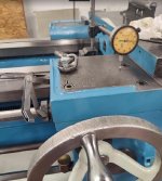
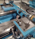
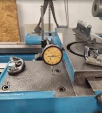
What I did so far was to first raise the apron side. Again, I'm working at the far right of lathe, where the bed is not worn. I raised using .020" feeler gauges and shims on each side of vee way, so lifting apron side on four corners of vee way basically. I had zero'd an indicator before lifting, and my reading in indicator showed about .027" after sitting down on the feelers and shims:

411.jpg

In doing that, I could also see the change on my level:

412.jpg

I then raised the taper attachment side. I used .015" shims at each end there.

414.jpg

This got me close to level. Also it dropped the apron side lower on my indicator reading by about .002", to .025":

413.jpg

The result from this has me at very acceptable backlash on pinion gear. It also reduced my hand wheel travel from 1-1/8" down to 5/16":

415.jpg

Now those I consider ball park numbers. I can surmise from all my readings that I probably want to raise carriage vee ways about .022"-.023", and raise the outer flat way about .017"-.018", to be super nice on the pinion back lash. But, i have a few buts. . .:D

The first but being those numbers are based on the four corners being worn, and the saddle no doubt having a bit of rocking horse wear on it. I'll be milling the carriage ways flat. I'll be using bronze to raise the saddle, not turcite. But regardless, I want to mill down to the lowest point of wear, and probably a little beyond. I'd just prefer to get those surfaces flat.

The next being, if/when I grind the ways, then I need to measure and keep track of those numbers. Then add those numbers to the .022" and .017" I'm already projecting needed.

Also, I think whatever final numbers I come up with, I should go slightly thicker on the new bronze bearing surface. Besides raising the carriage, and once done, I'll then need to work those surfaces to get carriage/cross slide perpendicular to the spindle in head stock. That will require some removal of material, so starting off slightly thicker is the way to go.
 
You may want to look at Moglice again. You can cast the material at the tailstock end of the bed and you don't have to machine or scrape the surface afterwards.

Don't fail to make sure the feed rod lines up with the support at the end of the bed before you commit to a saddle position. Look at the gap between the saddle and the bed at the back of the bed to help you set and maintain the alignment of the saddle to the headstock.

https://www.practicalmachinist.com/...addle-using-moglice-387480/?highlight=moglice
 
Also, I think whatever final numbers I come up with, I should go slightly thicker on the new bronze bearing surface. Besides raising the carriage, and once done, I'll then need to work those surfaces to get carriage/cross slide perpendicular to the spindle in head stock. That will require some removal of material, so starting off slightly thicker is the way to go.

If you are NOT "plating" the Bronze?

Starting off GREATLY thicker, not "slightly" is the way to go!

It machines easily enough. It will be easier to prepare in thicker section.

Not cheap, Bronze. But the ways are actually rather narrow, so it ain't all that much Bronze.

And your time is more valuable than the chips.

Thermite is right, thicker is better, and look for a mechanical enhancement of the bond, like linear groves on both the bronze and the saddle or even recessed brass screws, pockets, or dovetails. Use an epoxy formulated for metals, not just the generic stuff. Masterbond has special formulas for various metals, 3M and Loctite have similar lines but more confusing guidance for selection. Before you glue, clean, clean, and clean more. You cannot have any contamination. If you have the capacity machine the bronze to final dimensions after glue-up on the saddle.
 
The result from this has me at very acceptable backlash on pinion gear. It also reduced my hand wheel travel from 1-1/8" down to 5/16":
As a general rule of thumb, for 14.5* p.a. gears, move them 1.4 times the amount you want to change. That is, if you have .005" lash and want .002", move the parts closer together by .0042".

For 20* it is about 1:1 e.g. to reduce by .003, move in .003

That's not exact but will get you close.
 
You may want to look at Moglice again. You can cast the material at the tailstock end of the bed and you don't have to machine or scrape the surface afterwards.

Don't fail to make sure the feed rod lines up with the support at the end of the bed before you commit to a saddle position. Look at the gap between the saddle and the bed at the back of the bed to help you set and maintain the alignment of the saddle to the headstock.

https://www.practicalmachinist.com/...addle-using-moglice-387480/?highlight=moglice

That's another great thread from you, and very nice btw. I do know people have had great success with both Moglice, turcite, and others. I do have practical reason's for wanting to use bronze, and went into some detail back in post #13 of this thread:
Monarch Series 61, Rebuilding for Improvement

But even outside those reasons, I feel like its more of a quest at this point :D. Attempting to use all metal, and do it with bronze just happens to a particular goal in itself to me.

Great point on the bed end bearing for all the rods. And a good idea on the short shaft for alignment, I hadn't considered a short shaft.

That end bearing and alignment was on my mind though. Its the primary reason I went ahead with addressing the bushings in end bearing, apron, and qcgb first, before doing this part of the evail. I wanted the rods in place with good bearings, in the hope it would help guide my alignment, plus give me indicators if I was out of whack. I hadn't got a chance to post on it yet, but I did plan giving some details.

Again, in raising and measuring the carriage I was working at TS end. Primarily to be up on good way surfaces. Secondary benefit, it put me close to bed end bracket, where the rods will be stiffer and less flexible:

416.jpg

Aside from checking pinion backlash to bed rack, I kept rotating the 4 shafts. I did this to feel if I was beginning to bind or strain from possible misalign. Spinning the leadscrew is nearly irrelevant, it mostly touches nothing until half nuts are engaged. Though there are a bit of guides on the half nut gibs:

419.jpg

Those guides are fairly close in ID to lead screw OD, but nothing like bearing closeness. The other 3 rods are much closer in fit though. After getting close to end bracket, and in raising carriage, I kept rotating all the shafts. It just felt right to me as I rotated, no binding or tension. I suspect the rods and end bearing were doing the work for me to stay aligned.

Another detail I can tell you, each of those rods are over 7' long, and there is some sag to each in the middle of them. I had grand illusions of using indicators to measure the rods on this alignment, and make some height and depth gauges out of sheet metal. Those I would use between between bed and each rod for horizontal, and one for under bed way to rod for vertical. In my head it was a good idea, but seeing the sag and flex, I'd be wasting my time.

Nothings bent, or out of whack. But with each rod more than 7' long, I'd be chasing my tail on that:

417.jpg

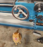
Shop cat coming from a rough a neighborhood has a foul sense of humor. Hard to get anything done when he's telling dirty jokes and laughing all day. He drinks on the job a little too. . .

418.jpg
 
Thermite is right, thicker is better, and look for a mechanical enhancement of the bond, like linear groves on both the bronze and the saddle or even recessed brass screws, pockets, or dovetails. Use an epoxy formulated for metals, not just the generic stuff. Masterbond has special formulas for various metals, 3M and Loctite have similar lines but more confusing guidance for selection. Before you glue, clean, clean, and clean more. You cannot have any contamination. If you have the capacity machine the bronze to final dimensions after glue-up on the saddle.

My current thinking is I will glue to assist, but it won't be the primary place holder. I'm going to drill and pin the bearings to the carriage ways. Probably two pins per each side of carriage wings.

Also, the pins will also be 932 bronze, threaded with taper heads. Something I need to make. But I'll screw the pins in to hold the new bearings in place. Then mill the whole kit and kaboodle.

I'd like to retain about a 1/16", or .065" on bearing thickness. Not sure how much the taper head screws will be holding at that point, so I thought I'd glue as well, to help hold while milling.

It is a balance between weakening the casting and the thickness of the wear plate. If it was my lathe I would shoot for .100" - .125" wear surface. I think you can get away with that. you would need more than that for screw holding only, your only choice is a combination of mechanical and glue. BTW the pins are a great idea, both for strength and easy locating. When you watch from Peter's machine shop the next owner replacing it, they will have to machine off the dang thing anyway back to the cast.
 
No need of threads. Nor even heads. Gravity exists. They are captive.

:D

Original intention was straight dowel pins. My reason for taper head screws and glue is for my clamping force when milling.

The c932 stock i can buy easily is 1/4" thick. I may mill some sort of oil relief in the center of each. But I'm starting with roughly a 2" x 24" long piece.

I have not come up with a reasonable way to clamp that down on mill by itself. And if lets say I'm taking it down to .100", i cant guarantee it'll stay down and flat.

I was thinking with it secured to carriage, i could mill it without it warping, or rising.

In searching around, i did find thinner strips ready to go. But they are copper or brass, not 932 bronze. Might be they're somewhere, i just didn't come across it.

Current intention is 932 on carriage, and 954 on TS.

You and i discussed the thermal expansion in another thread, with maybe one fixed pin, and another with an oblong hole to allow for expansion/retraction. I like that, but i still need to be able to clamp down somehow.
 
Look at the gap between the saddle and the bed at the back of the bed to help you set and maintain the alignment of the saddle to the headstock.

I was thinking about your suggestion, and guessing with Moglice you need the set screws and measures as you're sort of floating the carriage till the Moglice hardens.

I got to thinking more about headstock alignment, cross slide being perpendicular to spindle etc. And was thinking I might want a reference measurement just to know where I'm at before I change anything. Taking a measure of that gap near the headstock had poor results, presumably due to the way wear there. I'm also assuming that the gap should be close to even on both HS and TS sides. Near the head stock I measured about .013" on TS side, and about .028" on HS side. Again assuming way wear throwing me off.

Moving the carriage to tail stock end the ways are pretty nice. No surprise, my readings were much closer. .023" on TS side, and .026" on HS side. As viewed from rear of lathe, behind taper attachment:

435.jpg

I have a long way to go first, but one thing I liked with nt1953's thread is he worked to get his slight slant of cross slide to spindle face by working the carriage ways. In it, his goal or end point was .003" concave on total cross slide travel. To give facing cuts a very slight concavity. Much preferred than convex. And again, he's getting the slight tilt from the carriage itself to bed ways, much easier to manage this way. His mention here:
Repair of Monarch Series 60/61 Saddle Using Moglice

In Harry's another new toy thread, his expectation is .0005" inward slant over 12" for a slight concavity. I don't know that I'll be able to hit that number :D. My goal when I get there is hopefully within .002" and I'd like to fall in between .001" to .0015". Harry shows checking fairly well. His choice to adjust was more difficult though. He scraped the carriage's dovetail ways for cross slide. And he commented on the difficulty. Good reading for anyone interested:
Another New Toy
 
Relative 'difficulty', can be. "It depends".

Cross needs scraped, regardless?

It has one Helluva lot less mass to manhandle onct the carriage has been sorted.. and not all that much surface-area.


Cross wudda had to be done FIRST... as the defining reference?

Then maybe done OVER?

Cross slide itself is easier to handle, but scrape it any way you want, it won't change cross slides angle to HS spindle when doing facing cuts.

The dovetail for cross slide, that is on carriage provides the direction, whether you have concave or convex on facing cuts.

Cross slide is the train, dovetail on carriage the tracks. Move the tracks directly, or just slightly turn the whole carriage to also move the tracks direction.

Working upside down on that dovetail is murder. Yes less realestate, but the exertion and time required is like 10x. Part of scraping is watching what your doing as you scrape. Very hard to do on a dovetail. You scrape and bend over to look. And you need a flashlight, because the dovetail itself is blocking the GD overhead lights :D.

Best option if choosing to work that dove tail, is to stand the carriage on end, so you can kinda sorta work straight down, and light can mostly get in naturally. But now you're still rigging the carriage on and off the machine to do checks and scrape.

Dovetails pretty much suck to scrape. Think I'd prefer milling it straight to get wear out, add some flaking for lube and be done with it. Just try to scrape high spots down for good contact.

I feel pretty sure working the carriage's bed vee ways will be easier than the dove tail, to get a slight turn. But I'll see what it looks like when I get to that bridge.
 
Before I get to saddle, cross slide, and such, I will need to address other things first. Just talking it out now.

First and foremost would be the bed ways. "All things serve the ways" as I've heard it said.

Next in line after that would be headstock alignment to bed ways. As the cross and tailstock will need to be adjusted relative to spindle position.

Which brings up my next check. Checking headstock alignment to bed ways. I'm not particularly scared to lift the head stock on anything. I've had this head stock off already, and will do so again shortly.

I think popular theory is "that if you don't lift headstock, the alignment won't change". I don't think I could possibly disagree more. Things change. Machines get moved, maybe many times. Bumped in to, and all sorts of abuse, be it careless or accidental over the lifetime, which could be many many years. Also cast iron changes and grows. Test cuts can tell you something, but without jamming a test bar in the spindle, you will have unanswered questions. You simply don't know which way the spindle is pointing if you don't check.

One of the greatest accuracy improvements you can make is "getting everything pointed at center". Even with obscenely worn ways you can improve accuracy by getting head stock pointed at center, or even adjusting headstock to more closely fit the current bed wear.

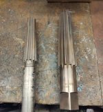
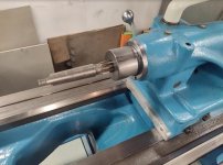
I'm only doing a check now to see where I'm at, the real adjustment will come after bed ways are addressed. Getting started, I first want to lightly clean up spindle taper. I will do tail stock quill while I'm at it. The headstock taper on this machine is a No. 5MT, and the tail stock is No. 4MT. Here's the finish reamers:

423.jpg

On my lathe I can fit long or short 5MT in the spindle. Talking to Mike Thomas, his 13" Series 61 can only use the shorter 5MT.

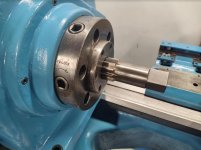
I'm not looking to bore out the spindle. Just looking to de-burr and get dirt out. Mostly just turning by hand with a wrench and light pressure:

424.jpg

Also doing the tail stock. Put a little more time here to clean up the taper. Tail stock tapers receive a bit more abuse.

425.jpg

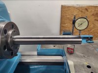
Test bar in, and running checks. I like my alignment checks from 4 points, at 12, 3, 6, and 9 oclock. 12 and 6 serving vertical, and 3 and 9 horizontal. Once I got my system down, I'll just check 12 and 9 oclock to see vertical and horizontal alignment.

Running the carriage with indicator mounted, to sweep the length of test bar. In this pic I'm showing .0055", but I had some run out, and indicator movement. After running the check a few times I'm calling it .004", and that is upward tilt of the spindle/headstock.

426.jpg

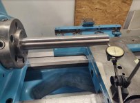
Running a sweep of horizontal at 9 oclock. I'm also calling it at .004", pointed toward rear of lathe:

427.jpg

So currently headstock is pointed upward by .004", and also pointed toward rear of lathe by .004". Again, I'm not adjusting now. But as I remove and reinstall headstock, I may take some corrective action to get those numbers closer to zero.
 
I'm sure you are aware that the surfaces between the saddle and the bed that you and I both used to play with the headstock to cross slide alignment should be without wear (see post #158). However, the gap will change as the carriage is moved because of front V-way/back flat wear. Additionally, when you use the saddle as part of the measurement system to see which way the headstock is pointing, you need to keep in mind that front V-way/back flat wear means that where the headstock points will be relative to the position of the saddle on the worn V-ways when you measure that pointing.

Problems with tailstock alignment are similar and compound the problems of alignment of the headstock.

I could not resolve this problem, so I mostly ignored it.

I felt like most of the workpiece facing would be near the headstock, so that is where I tried to get slightly concave face cuts. I remachined the tailstock base to be level and parallel at the tailstock end of the bed, but I know it is not aligned anywhere else. I tried to average the height of the tailstock over the bed length, and resolved to do my best to adjust front to back alignment of the tailstock when I needed to resolve taper issues. That still leaves issues of headstock/tailstock pointing issues when drilling or reaming. I don't know what to do about that. My lathe is worn and what I have done has improved things, but unless I regrind the bed, there will be alignment issues.

First I'll say my goal is "improved", not perfection. If I cut inaccuracies by half, I've already won. And I think I can do considerably better than cut them in half.

Working on our own we have no chance of reaching original factory specs of .00005" on total bed length specs, or whatever it was. But we don't really need that to do excellent work. Even with heavy wear I feel I can do great work if i pay attention, and do what needs doing.

But i also think I can grind inner vee and outer flat and be within very favorable numbers for the carriage. Vee for my TS is quite good, the inner flat looks ugly from saddle draging garbage on it, but spec wise, i dont think its out horribly.

To answer one point, yes i do think way wear has an affect on my head stock align reading, but I've accounted for it, plus run a sweeping test bar check, using tail stock besides using carriage. I still feel I'm pointed up by .004". But I'll re-run all this once i finish grinding the wear from ways.

On the tail stock what's helped me achieve really nice accuracy. . . Absolutely first, headstock align to ways. With that done, I adjust tail stock quill, not just to height, I adjust quill to be parallel to spindle. Or to hit my best possible gray area of paralell. If TS or ts base happens to come in level, great. But its a long distant 2nd. Quill parallel to HS spindle first.

I would normally sort that by checking TS at 3 locations. Up close to spindle/chuck, midway on bed, and at TS end. Average it out, and hit my best possible gray area for paralell between the three locations.

By rights, if bed is level, HS level and aligned, then you should be to just level TS base. But it dont work out too well if you align HS to account for bed wear, and hit that gray area in the middle.

In this case, i may grind inner flat for TS, which could improve things as well.
 
Before I get to saddle, cross slide, and such, I will need to address other things first. Just talking it out now.

First and foremost would be the bed ways. "All things serve the ways" as I've heard it said.

Next in line after that would be headstock alignment to bed ways. As the cross and tailstock will need to be adjusted relative to spindle position.

Which brings up my next check. Checking headstock alignment to bed ways. I'm not particularly scared to lift the head stock on anything. I've had this head stock off already, and will do so again shortly.

I think popular theory is "that if you don't lift headstock, the alignment won't change". I don't think I could possibly disagree more. Things change. Machines get moved, maybe many times. Bumped in to, and all sorts of abuse, be it careless or accidental over the lifetime, which could be many many years. Also cast iron changes and grows. Test cuts can tell you something, but without jamming a test bar in the spindle, you will have unanswered questions. You simply don't know which way the spindle is pointing if you don't check.

One of the greatest accuracy improvements you can make is "getting everything pointed at center". Even with obscenely worn ways you can improve accuracy by getting head stock pointed at center, or even adjusting headstock to more closely fit the current bed wear.

I'm only doing a check now to see where I'm at, the real adjustment will come after bed ways are addressed. Getting started, I first want to lightly clean up spindle taper. I will do tail stock quill while I'm at it. The headstock taper on this machine is a No. 5MT, and the tail stock is No. 4MT. Here's the finish reamers:

View attachment 339365

On my lathe I can fit long or short 5MT in the spindle. Talking to Mike Thomas, his 13" Series 61 can only use the shorter 5MT.

I'm not looking to bore out the spindle. Just looking to de-burr and get dirt out. Mostly just turning by hand with a wrench and light pressure:

View attachment 339366

Also doing the tail stock. Put a little more time here to clean up the taper. Tail stock tapers receive a bit more abuse.

View attachment 339367

Test bar in, and running checks. I like my alignment checks from 4 points, at 12, 3, 6, and 9 oclock. 12 and 6 serving vertical, and 3 and 9 horizontal. Once I got my system down, I'll just check 12 and 9 oclock to see vertical and horizontal alignment.

Running the carriage with indicator mounted, to sweep the length of test bar. In this pic I'm showing .0055", but I had some run out, and indicator movement. After running the check a few times I'm calling it .004", and that is upward tilt of the spindle/headstock.

View attachment 339368

Running a sweep of horizontal at 9 oclock. I'm also calling it at .004", pointed toward rear of lathe:

View attachment 339369

So currently headstock is pointed upward by .004", and also pointed toward rear of lathe by .004". Again, I'm not adjusting now. But as I remove and reinstall headstock, I may take some corrective action to get those numbers closer to zero.

Do you have one of these?

http://totallyscrewedmachineshop.com/documents/Testing Machine Tools (Dr.Schlesinger).pdf

Remember you are building a stack and every component has an impact. If you are ok lifting the headstock, verify if the bed is level with the portion under the headstock, i.e the worn part is not dropping too much relative to the headstock support. Somehow you want to know if the bottom of the headstock is coplanar with the axis of the spindle, and then you want to know if the taper is symmetrical to the axis. Every one of those can contribute to what you measure there :). Schlesinger gives good points on measuring things.


Back
Top