I believe I have read just about all the threads to this conversion.
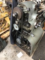
I have 1942 round dial 10EE. When I bought it the guts were gone and it was setup with a KB control 225D (9391) 230vac input 180vdc output. I have been running with this controller for many frustrating years.
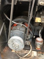
On a good day, going downhill, with the wind to my back, I can get 1,250 rpm. So says the dial tach. I forget it’s been a while, but I think the field winding is running though the original potentiometer on the base. That’s what gets me a little above 1000rpm. I am very interested in this conversion. I have the 3HP Reliance large frame DC motor. I have been studying the Parker/Eurotherm 514C/507 4Q SSD DC Retrofit into 1961 10EE modular wiring schematic drawn: MES. I do not have the ESLR control setup. I would think I would activate the original drum switch by the headstock.
So, my questions, which are many; has anyone repower this motor with this setup? My power source is 208vac 1ph. What do I need to do to boost my Voltage to 330vac? I do not have the “T5 plus boost transformer”.
I can manage electrician, but not electrical engineer. Any help would be greatly appreciated.
Dan
I have 1942 round dial 10EE. When I bought it the guts were gone and it was setup with a KB control 225D (9391) 230vac input 180vdc output. I have been running with this controller for many frustrating years.
On a good day, going downhill, with the wind to my back, I can get 1,250 rpm. So says the dial tach. I forget it’s been a while, but I think the field winding is running though the original potentiometer on the base. That’s what gets me a little above 1000rpm. I am very interested in this conversion. I have the 3HP Reliance large frame DC motor. I have been studying the Parker/Eurotherm 514C/507 4Q SSD DC Retrofit into 1961 10EE modular wiring schematic drawn: MES. I do not have the ESLR control setup. I would think I would activate the original drum switch by the headstock.
So, my questions, which are many; has anyone repower this motor with this setup? My power source is 208vac 1ph. What do I need to do to boost my Voltage to 330vac? I do not have the “T5 plus boost transformer”.
I can manage electrician, but not electrical engineer. Any help would be greatly appreciated.
Dan