What's new
What's new

A square hole question...

I like the idea of drilling the corners first as well
I had been going to suggest drilling down with a 4 flute center cutting end mill but using a drill first would make it easier to follow with an end mill of the proper diameter for the radius.
Sometimes raising the endmill out and stepping over then cutting down with the end of the endmill a few thousandths away from the finished wall a few times a bit like chain drilling sometimes can take most of the side pressure off the endmill to remove the bulk of the material.
Experimenting with some scrap pieces where you have very little to loose except maybe a small broken end mill will boost your confidence when it comes to the real thing.
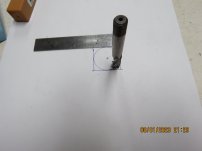
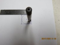
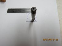
P.S. some times I have to kind of mock things up to see for my self what it looks like .
I think there won't be much room for you to drill the corner and still have material all around the drill to keep it from walking
if you cut down from the top using the end teeth of the endmill in the correct location for the corner radius and then a couple of other steps on either side of it you shouldn't have too much material to come off to finish the sides
 

Attachments

  • IMG_2479.JPG
    IMG_2479.JPG
    429.3 KB · Views: 7
  • IMG_2480.JPG
    IMG_2480.JPG
    469 KB · Views: 7
  • IMG_2481.JPG
    IMG_2481.JPG
    451.2 KB · Views: 7
Last edited:
Like Joe M, I've broken a few end mills. That is why I was very reluctant to try milling this but I will revisit the calculations and make a drawing or two. I may be able to go up to 1/2. The axle doesn't actually touch at the corners. The original parts are not all that precise by the standards even of the 1920s and the large diameter axle is positively huge in comparison to the horsepower generated. This is all consistent with engineering before WWI. These engines produced a lot of torque at relatively low rpms. 50hp was considered big but a 50hp engine could easily move a very heavy car. But, these figures are very deceptive since the hp formula was quite different than is used today although they still depended on low rpms and great torque. This car was, when new, rated at 35hp and displaces just short of 300ci....with the engine turning at 2000 rpms the car would be moving at 63mph...faster than you would reasonable want to drive it. It's a fallacy that these cars putted along at 25 to 30...they didn't, but in 1910 there weren't many roads you could do 50 on for any length of time in. I'd like to be able to sustain 45 and go a bit faster if I absolutely need to. Keep in mind that the vast majority of "restored" early cars are mechanically worn out with fancy paint & upholstery.
 
Did you say what size the center hole is? You might drill it out to 1" or even 1 1/16" just to have less material to remove with the end mill. You might need to drill the corners first depending on sizes.
 
If I was in a re-education camp with time on my hands.

Use long and strong 5/16 endmill to rough out the hole.
The use a jig and a file to get the corner.
Doing a good job might get me released early. :drink:
 
I took the advice offered here to heart and gave it a try. This is a test hole in aluminum. It isn't perfect but I am getting very close and it turned out to be easier that I'd expected. In order to control the length of travel I mounted an indicator on the mill table since the backlash in the screws would have made it a good deal more difficult. I'm pretty satisfied...this was done with a 3/8" end mill and the radius at the corners is just about perfect.
 

Attachments

  • Square Hole.JPG
    Square Hole.JPG
    299.1 KB · Views: 16
This is an obvious blacksmithing job.......pierce the hub ,then forge the square around a mandrel.......these parts were all made with drop hammers ,the round registers turned in a lathe.
 
Here's another question. I've never used a "roughing" mill. If I rough out the hole with one, can I then use a finish end mill to clean it up without changing the settings?
Not if I understand what you mean by "without changing the settings". In this situation you would rough the hole slightly undersized, maybe 0.010 to 0.030" inside the desired profile, then finish to the desired profile. So X and Y coordinates will change. On the other hand, if you have a spindle RPM and feed that works for the rough cut, it will work for the finish cut. I'm going to assume you took the rough cut in several depth passes, in which case you should rough closer to the desired profile (i.e., 0.010") so a single full-depth finish pass doesn't overwhelm things.
 
" the hp formula was quite different than is used today"
I'd be really curious about this. Engineering units are somewhat sacred as are their conversion factors to other systems of measurement. For instnace, 746 Watts/HP is one of those conversion factors that was drilled into my thick head at a very early age. Did they redefine a HP since the early 1900's?
 
The term itself was first introduced by James Watt in relation to steam engines. In the early 20th century there was little agreement on how it could be applied to internal combustion engines and several different formulas were used, none of which conform to the current manner of measuring HP. I'll have to look around and find one or two...but as an example of how poorly it was understood, the British HP tax was calculated with a formula that included the diameter of the bore but ignored the stroke. As a result, the British developed long stroke engines because these enjoyed a lower tax. The famous 30/98 Vauxhall, a Laurence Pomeroy design, had 30 taxable HP and developed 98 HP. Early engines, like steam engines, developed most of their power through torque...by modern standards they were slow turning but still developed so much torque that they could be very high geared.

I am not an engineer so I find it a bit difficult to explain but something like a 50HP Simplex "speed car" had 4 pistons that were 5-3/4" in diameter with a 5-3/4" stroke. I don't know what the gearing was but the tires had an OD of 36" so when an engine like this was turning 2000 RPM the car was really moving.
OK, I think i understand. You're referring the computing the HP of a machine based on the design of the machine,
 
Honestly, that original hole looks like it was drilled with a Watts drill. Seriously.

However...
it appears big enough to use a 1/2" end mill and still keep the corner feature?

The way i do things like that on a mill instead of on a shaper, is set it up centered on a rotary table.

First, figure out the corners theoretically, and step inside the amount of the radius of whatever drill you want to use. Perhaps the same size as the EM that will be used for the straights. Center drill all 4 corners using the rotary function. Then drill. Perhaps a little undersize. Then set one side (2 corners) dead parallel to the x axis mill travel, and set the table stops

Then mill out the center using Y for distance, and using X for cutting. When y is near to final ID I climb cut the last pass, and come back conventional to avoid deflection in the wrong direction (which would be coloring outside the lines, so to speak). Retract quill, rotate table, plunge, . lock Y, climb cut and back with X, etc.

With a shaper you can more or less do the same with part vertical and a backstop for the Rotary to resist the cut. On a deep cut with sharp or small radius corners the shaper wins with less deflection, but some deflection will exist with either tool.

If you do it on a mill and have never done it, do yourself a favor & work a test hole on scrap of the same type of material the whole way through, so you can ID preferred tool (drill and EM) size, and how you have to position the corner defining holes inside the (imaginary) lines, etc. How to waste the center, and yet end up with table stops set exactly where they need to be.

Good luck!
 
You can cut the square on a Bridgeport with a rotary spacer. It is a bit picky but not impossible. Tilt the head both ways to be tangent to both inclined surface. Do one corner just past center both ways, then index to next corner.

View attachment 397524

This is a dihedral angle situation. For a three degree taper you won't tilt to 3 degrees but will be a bit off. I can't remember how to figure that, not even with CAD. But I'll bet someone will chime in.
I think you are referring to compound angles. There is some info in the Machinery's Digest on how to figure them.
JH
 
Honestly, that original hole looks like it was drilled with a Watts drill. Seriously.

However...
it appears big enough to use a 1/2" end mill and still keep the corner feature?

The way i do things like that on a mill instead of on a shaper, is set it up centered on a rotary table.

First, figure out the corners theoretically, and step inside the amount of the radius of whatever drill you want to use. Perhaps the same size as the EM that will be used for the straights. Center drill all 4 corners using the rotary function. Then drill. Perhaps a little undersize. Then set one side (2 corners) dead parallel to the x axis mill travel, and set the table stops

Then mill out the center using Y for distance, and using X for cutting. When y is near to final ID I climb cut the last pass, and come back conventional to avoid deflection in the wrong direction (which would be coloring outside the lines, so to speak). Retract quill, rotate table, plunge, . lock Y, climb cut and back with X, etc.

With a shaper you can more or less do the same with part vertical and a backstop for the Rotary to resist the cut. On a deep cut with sharp or small radius corners the shaper wins with less deflection, but some deflection will exist with either tool.

If you do it on a mill and have never done it, do yourself a favor & work a test hole on scrap of the same type of material the whole way through, so you can ID preferred tool (drill and EM) size, and how you have to position the corner defining holes inside the (imaginary) lines, etc. How to waste the center, and yet end up with table stops set exactly where they need to be.

Good luck!
That is just about exactly how I did it. I can't quite drill the corner holes because the hole in the center comes too close so I've been doing them with a center cutting end mill. And, this is a test piece...I have two more to do as well before I do the final pair just to refine the technique.


Back
Top