What's new
What's new

Designing a horizontal bandsaw from the ground up

Halcyon

Aluminum
Joined
Jul 17, 2022
Alright, so some background.
1. I like to make accurate miter cuts, often.
3. I have a lot of free time.
4. I'm not an engineer, I just played with legos a lot. Don't trust anything I say.
5. If this seems incomplete, it's because it is! This is a work in progress and will change often.

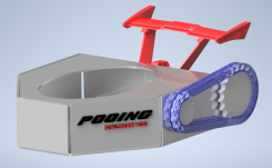
I decided to undertake the challenge of designing a horizontal dual mitering bandsaw that can be built from a single sheet of 1/4" plate, IKEA style. Doable? Ehh. Fun to try? Ehhhhh.

Firstly I needed to establish the constraints of the project.
1. Should be predominantly laser/waterjet cut plate components. Minimal manual fabrication, just MIG welding/assembly.
2. Should use no specialty components. Only readily attainable Ebay, McMaster, whatever. No castings. No machined parts(yes I realize the irony).
3. Adaptable to a variety of different parts. Motors, bearings,etc. Will be relying heavily on SLOTS and PILLOW BLOCKS. No press-fits here.
4. Be relatively easy to assemble for a novice fabricator. Be adjustable to account for tolerance errors.
5. Have a cut capacity of +/-60 degrees or better.

I started with research and studying existing designs. Dry vs wet. Crowned vs flat pulleys. Desired feature sets. I settle on some constraints and get to work.

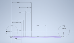
I start with a basic sketch and establish some base parameters. I intially started with larger wheels, but decided against it. The larger the wheel, the more material and gear reduction is needed.
1676795811864.png
1676795915559.png


I model some stuff and do some (probably ill-advised) Salvador Dali stress simulations.
1676796040495.png1676797300643.png


I widdle away at material and continue to run stress analyses. Eventually I scrap the whole thing and begin anew because I have some qualms about how it's progessing. I size the 14 inch pulleys down to 12 inch to save on material and gear reduction needs. The cut envelope is still insane.

I'm optimizing for material usage here, so it's rather important to save material and make nest-able geometry.
1676796247314.png

To make the design more nestable on sheet, I break the pulley down into smaller chunks. They consist of a central wheel with two layers of um..pentadrants? Holes added for clecos/bolts/etc. They are meant to go together as weldments, so the holes are more for temporary indexing than fastening.
1676796333952.png

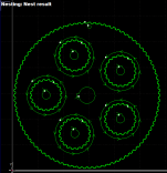
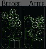
I drop the cut files into the nesting program just to see. It makes a remarkable difference.
1676796768919.png


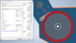
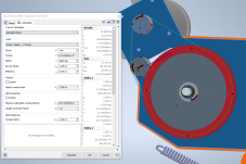
I ponder the gear system a bit. Gearboxes are really expensive. I play around with the Inventor Synchronous Gear Transmission tool. I mess with some different belts and pulley configurations until I settle on a 4.5:1 pulley system with an idler for tensioning. Since I'll be using a VFD to achieve the final RPM I'm only trying to get in the ballpark with my gear reduction.
1676796477214.png

Now I know what you're thinking. That drive pulley is going to cost like $8000 to manufacture. But using similar principals as the blade wheels, I chunk it down into bite-size bits. I add circular cutouts to the driven pulley, and that readily makes a nice little home for the drive pulleys to nest.
1676796586642.png1676796914049.png


to be continued
 
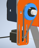
I see the price of hydraulic downfeed cylinders and resolve to come up with something cooler. I dive into the pulley ball pit again and emerge with this clusterfu. I have some halfbaked notions to implement a stepper drive downfeed. This is probably gonna be a whole separate thread on itself.

1676797644022.png

I model some adjustment plates, so that the pivot assembly can be aligned in the x and z. Also McMaster, for graciously providing 3d models. the shaft collars, oilite bushings, thrust bearings, motor, most of that detritus is from McMaster and they have my utmost gratitude.
1676797686083.png

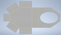
I start the tracking arm assembly in the sheetmetal space. I set the bend radius extra tight, then append manual cut relief to the flat pattern. This should make it so the design can be bent without a brake, and then welded solid.
1676797867139.png1676797902632.png


That's all I've got for now! I still have a daunting to-do list..
1. Adding tab/slot geometry for the weldment
2. More stress testing
3. More nesting verification
4. More slots? More pillow blocks?!
5. Spec correct counterweight springs
6. Design the pitch control stepper programming/circuitry
7. Idler assembly
8. Gussets n whatnot

1676797971299.png
1676798688327.png
 
Last edited:
ok, to begin. Not enough meat anywhere. not even reasonably close.
14 inch wheel running at 87 rpm at 60 hz nominal is not happening with single belt, or even two belts.
If you are concerned about material cut out on a sheet of steel - move to 1/2'' blade. Lot less motor (1hp!) - and lot less gear reduction with smaller wheels. lot less blade tension. guide arms can be smaller, still bigger than what you have. by my numbers a 1 1/4 x 3/4 solid over 8 inches was minimum material on 1/2 blade. what is holding guide arms rigid to hinge pin is the guide force diagram. how do you adjust guides for true and square? how do you true and square your wheels if they are riding flange pillow blocks?
vice? double or single?
driving off the hinge pin takes a lot of torque, a whole lot squared. exposed belts are going to dissolve in saw shavings and are nono safety.
wheels without machining? cooks saw out of alabama sells nice premachined and balanced wheels...cheap. runout is measured in sub thousanths on wheels to axle. even cheap harbor freight ones are sub 2 thousandths. Also rim is parallel to axle, not kinda close.
coolant?
no matter how accurate your wheels and bearings your tensioner blade needs float.

good luck, you have a ways to go.
 
ok, to begin. Not enough meat anywhere. not even reasonably close.

Indeed, I do plan to build out the frame. I plan on using 1018 sheet.

14 inch wheel running at 87 rpm at 60 hz nominal is not happening with single belt, or even two belts.

Why? I'd like to learn more about this. Do you have some reference info I could delve into? I noticed marked difference between T10 belts and "L" cogged v belts.

If you are concerned about material cut out on a sheet of steel - move to 1/2'' blade. Lot less motor (1hp!) - and lot less gear reduction with smaller wheels. lot less blade tension. guide arms can be smaller, still bigger than what you have. by my numbers a 1 1/4 x 3/4 solid over 8 inches was minimum material on 1/2 blade.

I plan on going with a 1hp motor. When you say 'by your numbers', again, if you have some reference mtl I'd like to see! I was planning on adding flanges to the tracking arms to stiffen them. Even cheap HF saws running 1/2" blades seem to have 3/4" minimum thick castings for that application,

what is holding guide arms rigid to hinge pin is the guide force diagram.

I'm not sure I understand.

how do you adjust guides for true and square?

I could potentially add some adjustment screws to that assy' to allow for fine adjustment.

how do you true and square your wheels if they are riding flange pillow blocks?

I have bronze oilite bearings on the primary frame plate in addition to the pillow blocks. As far as fine adjustment I haven't come up with anything.

vice? double or single?

Actually, was planning on having slots on the vise backer plate and using Stronghand clamps in lieu of vise.

driving off the hinge pin takes a lot of torque, a whole lot squared. exposed belts are going to dissolve in saw shavings and are nono safety.

I had not put much thought into this system yet. I considered maybe using a lead screw off a cam to get more leverage.

wheels without machining? cooks saw out of alabama sells nice premachined and balanced wheels...cheap. runout is measured in sub thousanths on wheels to axle. even cheap harbor freight ones are sub 2 thousandths.

I'd like to avoid outside purchased parts as much as possible, as I would like to distribute this to the larger fabrication/maker community. If it's possible to build the wheels from a laser cut weldment I'd prefer that. Could one compensate for looser tolerances on wheel geometry by using tires?


Negative, just dry stick w/ air blast.

no matter how accurate your wheels and bearings your tensioner blade needs float.
When you say float, do you mean adjustability? Is this type of assembly adequate for that? I've got the bearings mounted to a plate that sandwiches over the main frame, with an adjustment screw.
1676803084931.png


good luck, you have a ways to go.

Haha thanks. Any feedback I can get is extremely helpful. I'd eventually like to get this perfected and make it available to the larger fabrication community, open-source if you will.
 
1018 gives zero benefit over a36. 41** for all parts in tension, 41** for parts in compression has better dampening- you can get out there and get better than cast iron with different alloys in different parts, *** stainless in tension, 10** compression, cast in torsion, gr * ti in varied. wood , like oak beam fiddle bow- big dampening force - if you are moving to open source and at least somewhat innovative. ***I am not giving away all my work.
what is difference in buying a pillow block and a wheel? There are other wheels out there stock, cooks is the best I have seen and very reasonable (cheap) price.
looser tolerence on a machine begs so many questions. would you try and design a lathe with a sloppy spindle? Only difference is a saw has stack up error and by definition is the rigidity of the tool (blade).
Your blade grows a few hundreths as it cuts, tension must be maintained, as blade back arcs the tensioner wheel needs to move in. fighting opposite directions simultaneously, float.

no coolant?

1 hp is not enough for 1 inch blade. sure, it cuts, but why use it? 1/2 inch blade can be driven with 1 hp and does not need the saw frame of 1". 1" will not cut straighter or faster or cheaper than 1/2"... it can, with lots of ifs and ands you do not have. 1" blade needs just over 1.5 hp at blade to run conservatively (very conservative, but not rubbing). That is at blade, not motor. a bridgeport can spin a 3/4 end mill poorly, it sings happy songs with a 3/8 bit - and has better mrr.

there are thousands of saw shape objects on the market for LESS than you can get the parts for (unless you are scrap yarding, which is cool- but....) .
 
What tension did you design around? I don’t see the frame you have taking a 1” blade to 20-30ksi. A smaller blade still sends 20ksi but it’s a lot easier to get it there.

Little wheels also reduce the fatigue life of your blade. My little saw’s teeth rarely dull before cracking.
 
I appreciate the desire to break stuff up to make it more nestable, but I really think you should re-evaluate where to do that. The wheels of a band saw are the most important part.

Also, that stepper drive downfeed. Whoo boy. I understand that you're not an engineer, but to do this project you'll at least need to know force and moment balances. Don't worry, the math there is simple. There's a reason that all the commercial systems, even the $700 harbor freight guys, use hydraulics rather than steppers. You could use a lead screw of some sort driven by a servo or maybe a huge stepper, but direct to the motor through that piddly little timing belt? Not gonna happen.

I think this is a fun project and I don't want to discourage you, but to get anywhere near the performance of a $700 harbor freight POS you're gonna be five grand in materials and 1000 hours of time into it. That's fine, that's the nature of development. But just understand that is where you're headed if you take it through to success.
 
Barring buying a used industrial saw, which is what I’d recommend, you need to reimagine that entire drive mechanism. There’s no way it will have the torque never mind the belt tension to pull a saw blade through any appreciably sized chunk of steel.

Why do you have an idler tensioning away from the drive and driven pulleys, creating only 90* of belt wrap on the motor? Reposition that closer to the motor pulley and run the belt on the opp side of the tensioner. It will still squeal like a banshee when it inevitably slips.
 
1018 gives zero benefit over a36. 41** for all parts in tension, 41** for parts in compression has better dampening- you can get out there and get better than cast iron with different alloys in different parts, *** stainless in tension, 10** compression, cast in torsion, gr * ti in varied. wood , like oak beam fiddle bow- big dampening force
Noted

- if you are moving to open source and at least somewhat innovative. ***I am not giving away all my work.
Fair enough. Just thought you might have access to some good reference material re the belt loading.

what is difference in buying a pillow block and a wheel? There are other wheels out there stock, cooks is the best I have seen and very reasonable (cheap) price.

I cannot laser cut a pillow block out of plate. I looked into Cooks, it seems the smallest wheel they sell is 19".

looser tolerence on a machine begs so many questions. would you try and design a lathe with a sloppy spindle? Only difference is a saw has stack up error and by definition is the rigidity of the tool (blade).
Accounting for adjustability with possible heat distortion.

Your blade grows a few hundreths as it cuts, tension must be maintained, as blade back arcs the tensioner wheel needs to move in. fighting opposite directions simultaneously, float.
Noted

no coolant?

1 hp is not enough for 1 inch blade. sure, it cuts, but why use it? 1/2 inch blade can be driven with 1 hp and does not need the saw frame of 1". 1" will not cut straighter or faster or cheaper than 1/2"... it can, with lots of ifs and ands you do not have. 1" blade needs just over 1.5 hp at blade to run conservatively (very conservative, but not rubbing). That is at blade, not motor. a bridgeport can spin a 3/4 end mill poorly, it sings happy songs with a 3/8 bit - and has better mrr.

there are thousands of saw shape objects on the market for LESS than you can get the parts for (unless you are scrap yarding, which is cool- but....) .

I'm going to seriously consider dropping to a smaller blade.

What tension did you design around? I don’t see the frame you have taking a 1” blade to 20-30ksi. A smaller blade still sends 20ksi but it’s a lot easier to get it there.

I figured 20ksi/700lbs at the wheel axles. Not sure if that's a sane number or not.
1676826955359.png

Little wheels also reduce the fatigue life of your blade. My little saw’s teeth rarely dull before cracking.

Should I bump them back up to 14"? Or larger?

Barring buying a used industrial saw, which is what I’d recommend, you need to reimagine that entire drive mechanism. There’s no way it will have the torque never mind the belt tension to pull a saw blade through any appreciably sized chunk of steel.

Why do you have an idler tensioning away from the drive and driven pulleys, creating only 90* of belt wrap on the motor? Reposition that closer to the motor pulley and run the belt on the opp side of the tensioner. It will still squeal like a banshee when it inevitably slips.

My understanding of pulley and belt systems is poor. I thought it'd be a neat alternative to a gearbox since the pulleys could be laser cut, and worth exploring at least. The belt in question here is a 25mm T10. Does this seem more sane? The 30ft-lb figure is entirely arbitrary.
1676828451803.png


I appreciate the desire to break stuff up to make it more nestable, but I really think you should re-evaluate where to do that. The wheels of a band saw are the most important part.
Do you think it's even tenable to build the wheel like this?

Also, that stepper drive downfeed. Whoo boy. I understand that you're not an engineer, but to do this project you'll at least need to know force and moment balances. Don't worry, the math there is simple. There's a reason that all the commercial systems, even the $700 harbor freight guys, use hydraulics rather than steppers. You could use a lead screw of some sort driven by a servo or maybe a huge stepper, but direct to the motor through that piddly little timing belt? Not gonna happen.

Yeah it's something I came up with after 3 or 4 bourbons. I guess what I really want is potentiometer controlled downfeed and automatic return. I like programming so it'd be something to keep me entertained for a bit.

I think this is a fun project and I don't want to discourage you, but to get anywhere near the performance of a $700 harbor freight POS you're gonna be five grand in materials and 1000 hours of time into it. That's fine, that's the nature of development. But just understand that is where you're headed if you take it through to success.

It's a fun project to keep me occupied following a surgery. I don't forsee this getting heavy industrial use cutting billets and i-beams. Rather hobby/light professional usage for cutting tubing.

I think it'd be amazing if anyone could download the plans, have their local laser shop cut out the parts, and have a reasonably accurate and affordable mitering saw. Plus each machine built here means less $$$ funneled to the communists. Fight communism with communism! Also buy war bonds.
 
Last edited:
My understanding of pulley and belt systems is poor. I thought it'd be a neat alternative to a gearbox since the pulleys could be laser cut, and worth exploring at least. The belt in question here is a 25mm T10. Does this seem more sane? The 30ft-lb figure is entirely arbitrary.

On a second look you also have the tensioner pulley on what will be the taut side of the belt, assuming you’ve designed this with the correct blade direction (toward the pivot).

I don’t think this will work without a worm drive gear box. The torque required is too great and your blade speed will be too hight for all but aluminum. In any event, serpentine belts are not superior to V-belts for torque transmission. Your relatively low speed and high tq application needs twin V-belts, B-series.

As an aside (not directed at you personally), I’m seeing far too many designs lately from junior engineers that are little more than flat-pack water-jetted or lasered crap . It’s like they never learned anything about casting or fabrication. Everything is some mis-applied flat pattern bullshit not fit to piss on.
 
Auto retreat is a multi-thousands dollar feature to do properly. When the “cheap” way of doing it involves a tigerstop you know it is not cheap.
tormach spent years and money on theirs and gave up with a proper motion and went with the oversimplified standard instead.

Head swings, vice stays rigid. Precision miter saws first word is precision. Floppy dangle stock is not how that happens.

There is potential in multi part wheels, no potential in straight from laser cutter.

A build your own machine kit is not a new idea. Some really neat ones out there. A saw is a machine with more moving parts than a mill, 3 of which must be exactly synchronized or you have saw shaped object if lucky- not a saw.

I am pro bandsaw, When i make a small miter saw it will be an abrasive. Good speeds, small footprint, and nothing cuts cleaner or straighter.
 
It's a fun project to keep me occupied following a surgery. I don't forsee this getting heavy industrial use cutting billets and i-beams. Rather hobby/light professional usage for cutting tubing.

That's the thing with bandsaws, though. The blade tension forces, and the moments and deflections they cause absolutely dwarf the cutting forces. You can't reduce the blade tension, realistically, because then you can't cut anything straight, tubing or solid.

So heavy industrial use cutting I beams isn't materially different than light industrial use cutting tubing.

For a given blade side, you need a certain amount of tension. That's more or less fixed. 700-1000 lb for a 1" saw.

If you redo your FEA model to have the constraints closer to right, you'll see that that tension is trying to bend the spine of the saw down rather a lot, and twist it some.

The bigger your blade, the more force 30ksi of blade tension requires.
The bigger your wheel, the more moment that amount of force causes to bend the spine.
The longer the opening, the more the spine bends for that fixed amount of moment.

The more the spine bends and twists, the harder it is to cut straight.
 
One of the best fabricators I've ever known used a miter saw for cutting tubing. Plain old carbide blade from the 'hardware store'. I figured steel tubing would eat it up at that speed, but he said they last just fine and they're cheap.

It's been too many years to remember for sure, but I think I used my 12" Dewalt to do the conduit I put up in my garage. I don't recall ever using a tubing cutter for anything but copper.

Wear eye protection, and avoid the bullets if at all possible.
 
Anyway, in light of #3, have you considered taking a used manual saw and turning it into an auto saw? That would make more a more interesting project, IMHO.
I'd like to see someone do an auto porta-band. I could see potential for small parts and tubing if it was done well.
 
You cannot cut a toothed belt pulley from steel plate. It will not work at all. Timing pulleys are machined so they are round and hobbed for the correct tooth profile. The ancient Doall C4 saws used a crude internal gear inside the bandwheel to drive the blade with a pulley set for motor reduction. It worked, but those saws are loud and sucky. You need to use a gearbox or atleast some real machined pulleys.

The spine of the frame should be heavy wall steel tubing.

You can't fab the bandwheels and run them without machining. No way in hell. Total fail.

Blade guides and support arms need total redesign.

IMO, if you want to do this, start with a real bandsaw. Something that is fabbed from plate. Reverse engineer it. Design around a lower cost gearmotor. Bandwheels, guides and guide supports will have to be machined or bought for an existing saw. No way to avoid that.

A shitty is such a horrible thing to use. I'd hate to see someone waste so much time and money building the worst bandsaw ever.


Back
Top