What's new
What's new

Gear cutting machines with pitch error correction mechanisms

Result was fatigue failure of the gear teeth.
Gear guys always blame the bearings :)

Not impressed by what they did in 1900. I mean sure, it was great for 1900 but to bring it up now as something we should be in awe of, meh. I mean this whole thread is "how to compensate for a crappy wormgear" when that hasn't been a problem in fifty years. All these methods are like "how to get the flat belts from slipping on the pulleys". Who cares ? (Except for antiquarian interests.)

p.s. Partly I am not impressed because some of that stuff is flatout dumb. That mechanism to advance the table wormgear -- why ? It's retarded. Set the index for one too few or one too many teeth, counteract that with your feed gears, and away you go, table worm advancing just like this weirdass machanism except no bullshit stuff needed. That's also been commonly known for ages, it's how you can make a prime change gear you don't have change gears for. This is a case of people being too clever for their own good.

Old stuff that serves a purpose and applies to what you can do today is great. I love old stuff that works. But things that are useless, it's like the best way to burn buffalo chips, only interesting as a quaint oddity.
 
Last edited:
"how to compensate for a crappy wormgear" when that hasn't been a problem in fifty years.
I would love to hear about precision (with a kinematic error of the order of 1-2-3 arc seconds) gear hobbing machines in 1973 - as far as I know, there were practically no CNC hobbers then.
Who cares ? (Except for antiquarian interests.)
Oh, as I already said - this is purely antique interest.
@Peter S Thank you so much for the pages from the book! Very interesting material.
 
I would love to hear about precision (with a kinematic error of the order of 1-2-3 arc seconds) gear hobbing machines in 1973 - as far as I know, there were practically no CNC hobbers then.
IT DOESN'T MATTER. YOU DON'T NEED THEM. THEY SERVE NO PURPOSE.

All that matters is the tooth-to-tooth spacing accuracy over three adjacent teeth.

If you want to do some radial spacing over an entire disk where extreme accuracy over the entire round thing is important, DON'T USE GEARS.

Just because I have a hammer doesn't mean I should pound screws in.
 
IT DOESN'T MATTER. YOU DON'T NEED THEM.
I get the impression that the precision worm gears once did something very bad to you.... I'm sorry, I really am.
I have already described the applicability of precision worm gears earlier in this topic and can repeat the simplest example (besides applications in astronomy, mechanical navigation systems, etc.): a worm wheel in the table drive of a gear hobbing machine. It has approximately 2 times greater kinematic accuracy than the best kinematic accuracy of the product processed on this machine. That is, obviously, it is impossible to take a “regular” gear hobbing machine and machine a worm wheel on it for yourself. Checking the accumulated tooth pitch error is one of the mandatory steps to determine the degree of gear accuracy; if there is no compliance with the tolerance, this is a defect.
In addition, I would like to remind you that even periodic tooth pitch error (not accumulated) has a similar tendency: it is impossible to make a worm wheel for machine X on machine X without losing the accuracy of the machine.
 
: it is impossible to make a worm wheel for machine X on machine X without losing the accuracy of the machine.
Actually, that's totally wrong. Unless you are cutting a wormgear of exactly the same size and number of teeth as the wormgear in the hobbing machine, it will do EXACTLY what the mechanism described by Peter S does, except all by itself with no additional mechanism. Tangential feed. Every rotation of the cutting tooth is in a different place relative to the table wormgear.

Also, normally, the table wormgear in a hobber, especially one intended for instrument use, will be larger or MUCH larger than the work. For instance, the wormgear in a 6-10 designed for instrument gears is ... I dunno, 12" in diameter ? 14" ? Huge, relative to the max size that the machine will cut (6")

All of which is moot, because nobody uses gears for this purpose anymore.

++++++++++++++++

p.s. Just to return to the article quoted earlier --

"Parsons had ordered the gear from a specialist company in England, the Power Plant Company, which did an excellent job for that period.

Parsons however landed in serious difficulties with the first gears of his own manufacture. They were extremely noisy with a piercing sound from pitch and mesh errors. There was also pitting and wear on the tooth flanks.

...he then invented what was to become known as the creep method ..."

A few points. One, other people were obviously capable of gears which worked fine. He bought the first set and they were a success. He cheaped out on the second set, built them himself, and because he didn't have a fucking clue, they were no good.

The conclusion drawn by the author that the screaming noise was due to pitch and mesh errors can't be verified, and is quite possibly incorrect. There are a whole lot of other possibilities, especially since he didn't know what he was doing (as evidenced by the screeching and howling from his home-made gearset.) Another thing that was obviously wrong was his material selection and heat treat. Pitting and tooth wear are not caused by tooth spacing errors. They are caused by an unsuitable material and/or heat treat. Probably both, considering he was a cheapskate idiot.

And last, no, the "creep method" is not what his dipshit idea is known as, because nobody does that silliness.

It's not "known" at all. It's a ridiculous mis-analysis of a problem caused by a guy who doesn't know shit and won't pay someone who does, as he so capably demonstrated. He made his own problem, which he then supposedly "solved" but we have no idea if he really did or not because it's highly likely that what he thought was the problem, wasn't. All he had to do was go back to the Power Plant Company and buy a decent set of gears that worked, instead of wacking off in his basement. Or knowing a little about victorian england, well ... all bets are off, but it probably involved young boys.

Parsons may have been great at turbines but he was demonstrably crap at power transmission. This doesn't seem to me to be the kind of person you'd want to take as an authority.
 
Last edited:
'The cause of this singing was explained by Sir Charles A. Parsons in a lecture delivered to the Institution of Naval Architects. Parsons also described an ingenious process, namely the "creep process", for avoiding it. This lecture seems to have been generally overlooked and even firms specializing in the manufacture of gear cutting machines appear to have remained ignorant of it, for only so is it possible to explain why again and again, helical gears cut on machines built by first-class machine-tool makers would sing when on load, sometimes to such an extent as to be quite unusable. .....
..... A fundamentally different way of avoiding the transmission of periodic errors of the table drive to the work-piece, if not entirely, at least to a considerable extent, is afforded by the "creep process" described in the above mentioned Parsons lecture
.

The Brown Boveri Review, Sept.Oct 1942, pp.276-289

https://library.e.abb.com/public/59...lWdnjqLX3gpQ6d1Af7sCRRmWwGDJ035zQXKR3ckURAQUK
 
'The cause of this singing was explained by Sir Charles A. Parsons in a lecture delivered to the Institution of Naval Architects. Parsons also described an ingenious process, namely the "creep process", for avoiding it. This lecture seems to have been generally overlooked and even firms specializing in the manufacture of gear cutting machines appear to have remained ignorant of it, for only so is it possible to explain why again and again, helical gears cut on machines built by first-class machine-tool makers would sing when on load, sometimes to such an extent as to be quite unusable. .....
Another half-wit (not you, Asquith. The person who wrote that). The "singing under load is not caused by tooth spacing errors. It is caused by the teeth bending and thus wacking each other as they enter the mesh.

You can verify this by noticing that they don't "sing" when not under load. If it were because of manufacturing spacing errors the gears would always sing, screech, howl, moan and otherwise drive you crazy.

That's why they invented tip and root relief.

Thus the reason that "no one ever heard of it, even first-class makers" was because it wasn't the problem.

Wrong analysis. Or as they say in the computer world -- garbage in, garbage out.

More evidence that Sir Charles Parsons was a dumbfuck as well as a cheapskate. The gears he bought from someone who knew what they were doing worked fine.
 
Last edited:
Actually, that's totally wrong.

Also, normally, the table wormgear in a hobber, especially one intended for instrument use, will be larger or MUCH larger than the work. For instance, the wormgear in a 6-10 designed for instrument gears is ... I dunno, 12" in diameter ? 14" ? Huge, relative to the max size that the machine will cut (6")
An angle is an angle everywhere :) An error of 100 arcseconds will be an error of 100 arcseconds on both a 20-inch diameter and a 10-inch diameter. Of course, in absolute linear dimensions these will be different numbers.
Tangential feed. Every rotation of the cutting tooth is in a different place relative to the table wormgear.
Yes, but the difference won't be that big. How many degrees will the workpiece rotate relative to the worm wheel of the machine? 30 degrees?
All of which is moot, because nobody uses gears for this purpose anymore.
Yes, damn it, thank heavens - no one NOW uses gears for precise rotation. But, alas, it was not always like this! The key (80-90%) source of kinematic error in a classic hobber is the worm wheel and the worm in the table rotation drive.
I studied the documentation of more than a dozen gear milling machines: both Soviet and those made in Czechoslovakia, England, and Germany. Everywhere the dependence is approximately the same: the accumulated pitch error of the worm wheel teeth in the machine is approximately 2 times less than the same parameter when cutting a test part on this machine.

As I already said, the approximate values are as follows: the accuracy of the wheel in the machine is 65 arcsec, the kinematic accuracy (without cutting) is 100 arcsec, the accuracy of the processed part is 130 arcsec. This is a completely normal situation for all types of mechanisms - especially for such complex ones as a gear hobbing machine with its numerous motion transmissions. The lead screw will provide movement accuracy worse than the accuracy of its thread. A rolling bearing will provide rotational accuracy worse than its geometric accuracy. To improve accuracy, a correction system was invented in the lead screws by turning the nut. And in hobbers - for example, the electronic system in the English UPH30 machine, from which I wrote earlier.

Next week I will go to the library of our university, I made a list of books like “a review of the machine tool exhibition in London/Chicago/Frankfurt”. I hope that there will be information I need there - for example, a detailed description of the Schiess model range.
 
Everywhere the dependence is approximately the same: the accumulated pitch error of the worm wheel teeth in the machine is approximately 2 times less than the same parameter when cutting a test part on this machine.
Sigh. Theoreticians refuse to accept reality. Here, once again :

It doesn't fucking matter.

This is like worrying about the concentricity of tires on your John Deere tractor.

For power transmission, the only thing that matters is tooth-to-tooth spacing over three teeth. The hob takes care of that. There is never more than three teeth in mesh. You could (theoretically) have .a half inch accumulated error over the whole part and it would not matter. There's only three teeth in mesh at any one time. (Yes, if the error is ridiculous the driven gear will speed up and slow down, woo-ooo wooo-ooo but as far as transmitting the power, if the load doesn't mind the gear won't mind.)

Howling and whining is not from tooth spacing error. They whine, clatter and howl under load because the teeth bend. Even if the spacing and concentricity were absolutely perfect all the way around, you would have this problem because stress/strain = deflection.

Past that, guess what ? It also doesn't much matter what the effing hobber does because high-load gears are heat treated. During heat treat they warp. Therefore, high load gears are ground after heat treat and the best grinders don't have wormgears or gears of any kind doing the spacing or flank generation.

This is like worrying about the surface finish on a forging. Guess what ? It all gets cut off so who gives a fuck ? IT'S NOT A PROBLEM.

See this ? you think this hummer is going to come out within 2 millionths on flat round and square ? You're dreaming.

IMG_2575.jpg

If your spacing were absolutely perfect, what's going to happen now ?

IMG_2951.jpg

Past a certain point, this "problem" simply isn't.
 
Last edited:
Therefore, high load gears are ground after heat treat and the best grinders don't have wormgears or gears of any kind doing the spacing or flank generation.
Tell me please, on what kind of grinding machine were the bronze worm wheels from the drive of the tables of gear hobbing machines processed? In addition, maybe I’m wrong - but in the table drive of grinding machines with a worm grinding wheel, a worm gear was installed. Yes, before CNC this was not the most accurate type of grinding machines - but (if I’m not mistaken and worm gears were used to drive the table in these machines) these are still grinding machines with clearly defined accuracy values.
Theoreticians refuse to accept reality.
Of course, I don’t have as much experience in gear machining as you do, but still, 10 years of gear machining does not allow me to be called only a theoretician....
Let me formulate the question again, as clearly as possible. What machines were used to process bronze worm wheels of AGMA 14 accuracy class in the 1950s in the USA?
 
My understanding is that mathis instruments made his own gear cutting machines long ago to build worm gears for telescopes. He died as i understand and there are a few remaining gear sets available. You may find more info on the internet archive than the current website. My dad bought one of their 18 or 20" aluminum worm gears in 2015.

5 arc seconds peak to peak , absolute error on the entire gear. How some 70 yr old guy figured out how to do that 30 years ago? Good question.

These days you can get better performance from a linear electromagnet motor.. and a 24 bit absolute position encoder.

I suspect there is a lot of information that is lost to history. For example.. the reduction gears for submarines were lapped by hand, by specialists who knew how to make the gears quiet down. Those folks are probably all dying off now. This is after the best manufacturers ground those gears.. Today, magnetic bearings are supporting the main reduction gears. My guess is the electromagnetic suspension has better dampening factor than journal bearings do.


So with regard to cams adjusting the tooth to tooth error and absolute error of a worm wheel gear cutter... Yes you would do that in order to generate a better wheel. I doubt such cams would be used to make a production run of gears.

An auto collimator and optical prisms would be used to check the absolute tooth positions, you could then average 3 generated worm wheels (by your cam adjustment mechanism) to make a better worm wheel to replace the one in your gear cutting machine. Then you do it again
 
Last edited:
These days you can get better performance from a linear electromagnet motor.. and a 24 bit absolute position encoder.
I guess you mean a high pole count rotary not a linear.
Yes you can buy high count encoders. Thing here with this is the needed perfect alignment of the disc to the rotary center.
Obviously the bigger the encoder scale the more room you get to play.

There is a cyclical error of each turn of the worm in such that has nothing to do with the wheel spacing.
Has to do with climbing the wall or contact point.
Luckily this is is somewhat know error wave. Not a nice sine wave but sort of.
Using test encoders and test runs we map this into our cnc software for each turn of the worm.
My first dive into this was to mount a simple laser pointer showing on the wall 30 feet away. Make small moves, mark and measure with calipers.
I think maybe this what the OP asked about.
As the worm wears or gets well used this changes.

No talk here now from me about the wheel or it's perfect spacing or center.
Baby steps... nail the worm/wheel contact error first. Then go after the wheel.

Why go nuts and do this? You are putting a radius on a small part.
A TPG 631 in the grinder. A whole lot or rise and fall that has to be right.
This is not just rotate. The other axis has to be in sync so servo lag and inertia problems.

Telescope people need just a position or some tracking.
Grinder people need all 360 degrees and all correct inside a 15-30 second cycle rotation.

I'm sure all here know these things so a waste of a post.
I do think I get the correction gizmos the OP has started with.
 
Last edited:
I do think I get the correction gizmos the OP has started with.
sure, i think they are 1940's era russian technology to make up for various failings in other areas.

just as a leadscrew can be mapped and a cam made to correct for the error, you can do the same for every rotation of the worm screw and gear.
there are many questions remaining as to what was the reason this was done. was it an intellectual exercise to make a better gear cutting machine or was it actually used in production to compensate for worn out gear cutting machines?
I guess you mean a high pole count rotary not a linear.
yes. but they don't need to be a high pole count. just a very fast, properly compensated control loop. the telescope itself might have a 1 second time constant regarding the maximum torque able to be applied by the motor, so if your control loop runs at 100khz and you have a 24 bit or higher encoder, you can maintain better than 1 arc second positioning, dynamically, before compensating with software to move the mirrors using piezo actuators.

the same technology could be used to produce better master gears.. but as emgo says.. who needs to.

in a sense my point is a 24 bit encoder is 12.9 bits per arc second. and the absolute error can be mapped out and corrected for.

a 22 bit encoder is like.. 600$
 
mathis instruments
It's them, right?
How some 70 yr old guy figured out how to do that 30 years ago?
Well, many of my colleagues are 70, some are already over 80 - and they are quite capable of designing something more or less modern :)
As I think I wrote earlier, in the process of searching for information I came across an interesting “hybrid”. The article was from 1990 or so. The point is that back then CNC hobbers still cost a lot and they were in short supply. At the same time, there were a huge number of mechanical hobbers in the industry, and PCs were already affordable. The article described a small unit that was built into the kinematic chain of table rotation.
In essence, it was an electronic version of the adjustment mechanism that I described earlier. A stepper motor, controlled from the LPT port, created additional rotation through several gears. You only need to measure the error of the machine worm wheel once.
For example.. the reduction gears for submarines were lapped by hand, by specialists who knew how to make the gears quiet down. Those folks are probably all dying off now. This is after the best manufacturers ground those gears..
Yes, for Soviet submarines these gears are lapped with abrasive for SEVERAL MONTHS. Everything to reduce noise. But I suspect that now they are still being lapped in assemblies - not a single grinding machine will ensure perfect uniformity of the gears in a pair, in the assembled state.
sure, i think they are 1940's era russian technology to make up for various failings in other areas.

just as a leadscrew can be mapped and a cam made to correct for the error, you can do the same for every rotation of the worm screw and gear.
there are many questions remaining as to what was the reason this was done. was it an intellectual exercise to make a better gear cutting machine or was it actually used in production to compensate for worn out gear cutting machines?
You see, I am quite ready to believe that these are some unique Soviet developments, in order to somehow do something without having precise machines. But I can’t understand where, for example, Pfauter got the worm gears for his hobbers :) Above, I already wrote about the English UPH30 machine with an electronic correction device, but I could not find its accuracy. So far, all the clues that I have found are the Schiess company, I’m still trying to get their catalog from the 1970s))))))
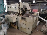
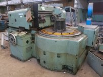
Regarding the issue of application: apparently, at first, corrective units were built into ready-made hobbers, both Soviet, English or German. I provided a picture on the first page. The reasons were primarily the need to increase the kinematic accuracy of the machine by 2-3 times; the issue of repairing worn-out machines was of secondary importance.
Around the 1950s or early 60s, a line of ultra-precision machines for worm wheels was developed and put into production in the USSR. They don't even have a spindle tilt, it's always horizontal. These were machines with maximum cutting diameters of 8, 31, 79 and 197 inches. Here are the first two, at 8 and 31 inches:
jdX1GaDJQl2PVM0ykBv3.jpg8xkDfMd1ajE89H3sry5A (1).jpg
Accuracy of model for 31 inches:
The maximum accumulated error of the processed wheel metric module M=6 Z=102 D=24 inches is 8µm (6arcsec)!
Then the two smaller models received improvements in the form of DROs, etc. Judging by the sales announcement, the number of machines of this type produced was about several hundred (I look at the serial numbers).
the same technology could be used to produce better master gears.. but as emgo says.. who needs to.
Now there are no problems with this! As you correctly noted above, direct drive with a high-torque motor to rotate the workpiece and hob + a good high-resolution encoder + calibration = accurate gears quickly, simply, reliably and repeatably.
On the one hand, I regret that I didn’t catch all these mechanical miracles - but on the other hand, I’m glad that now in industry these issues are being resolved with the help of CNC and good position feedback.
 
Last edited:
Old stuff that serves a purpose and applies to what you can do today is great. I love old stuff that works. But things that are useless, it's like the best way to burn buffalo chips, only interesting as a quaint oddity.
EmGo,
Can you give some examples of great old stuff that still applies/works today (I think you mean unchanged)? Genuine question.

When I think of mechanical stuff, e.g. machine tools, engines, vehicles, aircraft, power generation, printing etc, it has all been much developed from its beginnings. The four stroke principle still exists but you wouldn't use an 1876 Otto & Langen engine for anything useful. Involute teeth and gear cutting machinery has been around for a long time, but I doubt you would want to use those late 19th century machines. Steam locomotives, same.

Engineering development - new challenges met with better ideas.

I like to know about some 'old stuff' even though it has been superseded and yes there is a certain amount of awe at what was achieved in the past. It interests me to know how machinery has developed and improved. I know that most people couldn't care less but I'll pursue my interests.

Your criticism of Charles Parsons is ill-informed, he was a great engineer and with his company, gained the trust of shipping lines, navies, power generators and industries the world over.

He (and the other marine turbine manufacturers) would not have developed their own methods of gear cutting if they were already available and suitable. The 1909 "Vespasian" geared turbine was a moderate scale experiment for commercial ships. Direct drive marine turbines for naval and passenger ships were already established and much larger. As an example of the rapid increase of marine turbine power along with the need for lower prop speeds, just a few years later in 1916, John Brown (who had a Curtis turbine licence) received an order for the battle cruiser HMS Hood requiring 144,000 hp over four shafts, requiring four reduction gearboxes.
 
Millingman said:
What machines were used to process bronze worm wheels of AGMA 14 accuracy class in the 1950s in the USA?
Okay, so I'm going to remove my tentacle from this vortex in the time-space continuum and return to Reality. It's been fun but now time to return from ... the twilight zone.

EmGo,
Can you give some examples of great old stuff that still applies/works today (I think you mean unchanged)? Genuine question.
Sure. Not totally unchanged but almost ... we do physically make stuff better now :)

The 4-valve heads in your car ? 1913 Peugeout winner at Indianapolis.

You could say the transmission in a 1913 Model T is the modern automatic transmission. New ones are certainly more advanced but the principles are all exactly the same. And we don't have brass headlights anymore :)

There is one part in the Sportster parts book with a -15 number. The suffix is what year that part was introduced. Basically, an HD is a 1912 motorcycle that leaks less. They even had four-valves back then.

In machine tools, a 1960 American Tool Pacemaker is still the best lathe ever built :) That's now 65 years, can you believe it ?
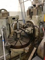
The maag grinders and shapers - maag started in the late 1800's, they are still as accurate as any of the latest greatest cnc grinders and shapers. In fact, as a small company if I were to play at grinding teeth, I could grab a 1950 (75 years old) Maag for next to nothing, because people nowadays only seem to know how to push buttons, and be totally competitive in accuracy with someone with a brand new Hofler for 1/100th the cost. Definitely slower but not 100 times slower.

I have a friend who, until very recently, was running production (small shop production but still 100 pcs at a time type) on a 1923 G&E hobber. They haven't changed. Until the very end of mechanical machines they did not change. Heavier built yes, but exactly the same design.

Here's another, 1920's or 30's ? Same machine, a little bit bone of contention, I prefer the modern equivalent twenty feet away which better get fixed soon ahem but the antique still runs fine, could use a wash job but still makes good teeth, close to 100 years old now ?

IMG_2176.jpg

The very latest 6-10 hobbers are not really any different than the earliest #3's, just sexier-looking. Don't know when they started, 1920's maybe ?

Fellows invented the gear shaper in the 1800's, until they changed to cutter-relieving they were exactly the same, just beefier. Lots and lots of those still running all over the world.

About three o'clock in the morning I'll wake up with a bunch more :)


Involute teeth and gear cutting machinery has been around for a long time, but I doubt you would want to use those late 19th century machines.
Would I *want* to ? No, I like the Brutalist design ethos. For appearance sake, I like 1950's, 1960's. As I mentioned, have friends who prefer antiques and they are happy using stuff from before our grandpas were born. If kept in good mechanical shape it works fine. (Not talking the space cutters, those are not a great idea and never were). In fact, for some one-off stuff there's machines from the teens or even earlier that would be desirable if you could find one. Just a few years ago I put in a 56" gleason bevel planer in taiwan from I dunno when, the twenties ? thirties ? - I don't think there even are any newer straight bevel machines that big. They built some weird generators that did spirals that would be killer in the single-part repair-replace market.

Engineering development - new challenges met with better ideas.

I don't think things have changed that much. Except for electronics, the ideas were all there a century ago. Capabilities have improved but not the concepts. Which is why I think patenting "ideas" is crap. Until you turn it into something real, it's bullshit. I have an idea for an instantaneous interplanetary matter transceiver, too :)

Your criticism of Charles Parsons is ill-informed, he was a great engineer and with his company, gained the trust of shipping lines, navies, power generators and industries the world over.
In some things, probly. But as far as gears go, he was an idjut :)

He (and the other marine turbine manufacturers) would not have developed their own methods of gear cutting if they were already available and suitable.
Unfortunately, the evidence is opposed to that statement. Your own article mentions that he bought his first set of gears from the Power Plant Company. They worked fine. Then he made a set that didn't work fine. Rather than going to people who knew what they were doing, this nitwit had to go on an ego-driven "inventing" spree where he didn't effing invent anything of value. His ideas have all turned out to be wrong.

While we're here, some of these cute stories are total bullshit. Maybe soviet sub builder lapped their gears for weeks, Westinghouse, in Sunnyvale, did not. I know people who worked there. No, they did not do that. It's oldfart horseshit. This whole thing with "lapping gears" is crap. Yes there are lappers (or were, many years ago). But they do not work the way people think. If you "lap your gears" together in your race-car tranny, all you are doing is wearing them out faster. Oh goody.

Oh. One little addendum. There's really two basic types of gear - power transmission and motion transmission. They are similar but different. The requirements are not exactly the same, so if you don't distinguish between the purposes, you're going to get all messed up. Big telescopes are totally different than ship reduction boxes. They do different things, so what's important to one is not so important to the other. When you conflate the two, you get things all mixed up. The machines to make stuff to rotate the telescope at Mr Palomar have very different requirements than the machines to make trannies for fifteen million cars a year. Like, airplanes and submarines both transit a fluid medium but they have different requirements. Power transmission and motion transmission is like that. Similar but different.
 
Last edited:


Back
Top