What's new
What's new

How to machine tube bending dies (half circle groove up to 76mm OD - 500m long)

Passmethehammer

Plastic
Joined
Feb 24, 2021
Hello.

New to this forum, hoping for enlightenment.

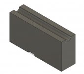
I make tube draw bending pressure and clamp dies for round tube up to 76mm (3 in) OD. They can be up to 500mm long. I currently 3D mill them, roughing with a flat end mill and finishing with a ball end mill, passing along the length with 0.05mm stepdowns. Then hand finishing the stepover, which can be laborious. This works for us, accurate enough, requires minimal setup/tooling investment and can just be left while I do something else.

I appreciate this isn't the correct way to do these to get a perfect half circle with minimal post machining finishing.

Ways I can think of:

Boring on the lathe
Boring on a horizontal borer
Boring vertically on a mill (end mill or boring head)
Right angle attachment on mill (end mill or boring head)
Horizontal mill with a convex cutter
Milling with large correct size ball end mill
Form grinding wheel (for smaller sizes only)

Each have their drawbacks but maybe a selection of the above are needed given the length, OD of tube and other dimensions - width etc (pressure die will be wider than clamps)

Can someone tell me (maybe with experience in tube bending tool making) their method for doing these. Are there any ways that I havent thought of that would work better? We have a 3-axis CNC mill and 2-axis CNC lathe.

Thanks.
 

Attachments

  • Pressure Die.jpg
    Pressure Die.jpg
    23.8 KB · Views: 119
Don't make a half circle, make a full circle. Make your part larger, drill the hole and bore for finish. Saw off the extra material.
 
For a short clamp as an alternative to 3D milling, yes I could and have in the past gone about it by having an over size block, drill, bore or ream and split. However, some of these pressure dies can be 250-500mm long to suit 10 to 76mm tube and could be 250x100mm in profile.
 
Do you have a manual lathe with at least a 1.0M carriage travel length? If so, you should be able to modify the carriage to have a fixture nest that would take your block and hold it longitudinally on the carriage, with the die bore on the CL of the spindle.

Then you'd need a long mandrel with a boring bit sticking out crosswise, with some method for adjusting the stickout and clamping the bit to create a line bore setup. One end of the mandrel is held by the lathe chuck, the other end by a center in the tailstock.

Then you feed the carriage down the length of the bed, with the die block being cut by the mandrel/cutting bit.

Obviously significant work to establish, but once the basic mechanism is done you can use spacers and clamps to mount a variety of die block sizes, and change mandrels/cutting bits to suit the desired geometry.

It's also much more stable to work with a full bore rather than a "C" profile, and use a double-sided cutter so there's minimal "push away" force during the cut. Work with a larger die block (and remove the waste), or do two blanks at a time, mated to create the full bore.
 
are these dies really supposed to be round? i had the impression they needed a special shape.
 
Milland - thanks for the reply. Line boring, after opening up with deep drilling/gun drill might work for larger tube sizes. Our CNC lathe can be used manually.

Dian - the dies we use for rotary draw bending are half circle, slightly offset to grip and apply pressure to round tube without touching the bend die.

I guess I really wanted know how this tooling is made by professional toolmakers without actually asking one. These benders have been around since the 1970s, there must be an industry standard method for making this tooling on manual machines.
 
If you have one of the "professionally made" dies, can you see machining tool marks that may give you an idea how it was machined ?
Regarding the line boring idea in the lathe - you can use a pretty stout boring bar in a 3" diameter bore.
We used to make boring bars and use a little boring tool insert with a fine thread, with a dial marked in "thous" for adjustment. Can't remember where we got them from.
 
In production, O bet they are made "by the mile" on a horizontal mill using radius form cutters.

That's how I would do it.
 
Thanks for the input.

We make these for metric tube/pipe sizes up to 50mm so 4,6,8,10,12,15,18,20, 22,25,28,30 etc, imperial up to 3" so 1/4, 1/2, 1, 1-1/4, 1-1/2 etc and NB pipe, 1/4, 1/2, 1" etc.

I believe most tooling, even from machine manufacturers is made to order. I doubt toolmakers we've used have form cutters for every size on a horizontal mill.

Some pressure dies can be relatively long (maybe 300mm) to suit a smaller diameter tube (say 25mm) for our benders without repeat pressure die followers to do U-bends with larger bend rads. Drilling and boring alloy steel (en24t) 25mm diameter at 300mm may be beyond me.

There are no tooling marks on bought in dies from a particular local toolmaker they look almost polished. Other toolmakers and the machine manufacturer we've used, look as though they have 3D milled both ways, length ways and up/down, leaving an almost grit blasted surface finish.

I'll just stick to the 3D milling, and possibly ask a toolmaker how they go about it. Some are old school, I doubt they use CAM but do have CNC.

Maybe in the future we will have a machine with faster rpm, not limited at 3000, and be able to go both ways without it taking forever. Leaving less to hand finish smooth. Still won't be a perfect half circle though, but close enough.
 
Best done on obsolete equipment to most of the world
Ether Planer or shaper Cake walk Old timer tools old heavy and ugly most of all large
 
CalG nailed it. I used to do repairs for an old time manufacture of tubing and pipe benders. Up to a certain size it was done on old horizontal milling machines. Once set up and running you could walk away as it slowly cut it's way down the work piece. Use coolant to clear the chips.
On larger radius dies they used a ancient planer with an 8' bed. They had special tool holders they could mount in either the lathe or planer that rotated the cutter through an arc. That required an operator to attend to the machine at all times. That tool was also used on the lathe to make the round dies as well.
When they shut down and the machinery was being scrapped out I grabbed a couple of those radius turning tools.

Mr bridgeport
 
i havent ever cast anything, but as an example bucket teeth of excavators or hammers of crushers can be made from self‐hardening bainitic cast steel (superior to hadfield because of higher ductility).
 
I used to machine a bunch of T and 90deg dies for industrial sized copper water fittings. Think 2-4" diameters, anyways, we 3d surfaced them and then hard milled and polished them. Used to be the cat's ass, been out of the loop for a while, but we used a Dapra inserted ball mill for roughing. That thing would haul ass is A2 and 4140PH. I think they have a standing promotion of buying 2 boxes of inserts and get a free cutter body. But, even back 10-15 years ago the inserts were $25/each. Tool just used one insert, half round, about 1/8" thick or so.


Back
Top