Hello
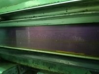
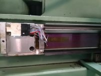
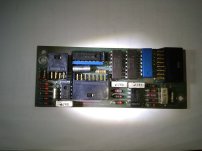
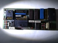
I have Ferrary CNC milling machine with SELCA control unit. There are 3 linear scales, and one of them is not working well...Doesn't increment in order when move axis, it generates for i.e 245, 246, 247, then again 245, then 259 etc... I opened it, and seems it is inductive linear encoder.... there are some op amplifiers and one blue 14 pins IC I can not find what is... 14-2-472 and B8004 is what I can read on its top... other two 18 pins ICs are 4051 analog multiplexers... Can someone help with similar symptoms... what this unknown IC could be? It is connected to coils below moving part.
Thanks

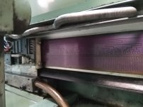

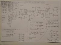

") - so it has to be one of the coarse-pitches channels (longer patches on the scale).
- so it has to be one of the coarse-pitches channels (longer patches on the scale).