Milling man
Hot Rolled
- Joined
- Aug 6, 2021
- Location
- Moscow, Russia
Hello colleagues.
On ebay we can find a large number of OMP400 probes at amazingly low prices - about $550 shipped from China. Of course, these are used probes.
We bought the first one about 3 years ago and it worked for 2-2.5 years. After that, he first began to show the "contact" state, when nothing acted on the probe, and then the LEDs began to glow blue - "I'm broken, send me to the manufacturer." We recently bought two more of these devices. One of them was immediately junk and showed a false positive, the second worked for about six months and also began to flash red when it should not.
It should be noted that the hMP x00 series is not a device with a classical circuit based on 6 balls and 3 cylinders. The stylus is based in them according to a similar scheme (3 balls and 3 prisms), but the signal does not come from the contact of cylinders and balls, but from strain gauges placed next to the balls.
When I began to think about how to fix this thing, I was faced with the fact that I could not even find photos of its insides on the Web! I think my experience will be useful to many who want to save money by buying a probe for 1/10 of the price of a new one.
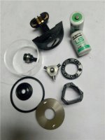
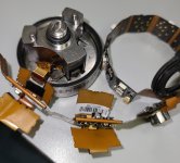
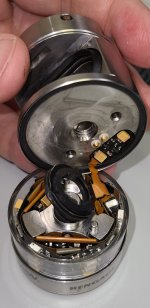
And so, problem number 1 - how to disassemble this thing? There is a flat screw in the battery compartment. You need to unscrew it CW, if you look from the side where the probe is attached to the spindle. The screw is screwed into the body of the probe and the two halves of the probe are in your hands. To unscrew this damned screw, I made a flathead screwdriver on the end of a hex wrench using an angle grinder. I had to make two such "screwdrivers", each turns the screw in a certain sector.
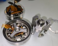
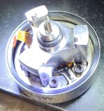
After unscrewing this screw, further disassembly is not difficult. Here is what the strain gauge looks like:


Black "drops" cover the silicon strain gauges. I destroyed one such "drop", it hid two strain gauges.
This node was in the very probe that broke down completely and burned blue - so I didn’t stand on ceremony with it very much. I forgot to measure the resistance of two of the destroyed strain gauges, but the other two show infinite resistance. Measurements on working at least somehow instances show 4.6-4.8 kOhm. From this part to the board there is a loop of 8 conductors - 2 from each strain gauge. As you can see in the photo, the strain gauges themselves are silicon strips glued to a steel base. Thin conductors went from them to the contact pads.
What I have already found out: the electronic unit from one probe works with the strain gauge unit from another probe. At least it doesn't flash blue immediately after being turned on.
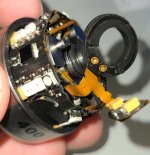
Now I want to solder the wires to the contacts of the block that I have already partially destroyed and replace the strain gauges with variable resistors. After that, I will try to get this Frankenstein to "work" with the electronic unit. If this succeeds, then I can replace the strain gauges with new ones, and solder a 100-200Ω variable resistor in series with each of them to match the resistance of the entire system.
I think this thing has some kind of service mode to calibrate the resistance of the measuring bridge at rest. There is a free connector on the board, apparently Renishaw can tune the probe through it.
On ebay we can find a large number of OMP400 probes at amazingly low prices - about $550 shipped from China. Of course, these are used probes.
We bought the first one about 3 years ago and it worked for 2-2.5 years. After that, he first began to show the "contact" state, when nothing acted on the probe, and then the LEDs began to glow blue - "I'm broken, send me to the manufacturer." We recently bought two more of these devices. One of them was immediately junk and showed a false positive, the second worked for about six months and also began to flash red when it should not.
It should be noted that the hMP x00 series is not a device with a classical circuit based on 6 balls and 3 cylinders. The stylus is based in them according to a similar scheme (3 balls and 3 prisms), but the signal does not come from the contact of cylinders and balls, but from strain gauges placed next to the balls.
When I began to think about how to fix this thing, I was faced with the fact that I could not even find photos of its insides on the Web! I think my experience will be useful to many who want to save money by buying a probe for 1/10 of the price of a new one.
And so, problem number 1 - how to disassemble this thing? There is a flat screw in the battery compartment. You need to unscrew it CW, if you look from the side where the probe is attached to the spindle. The screw is screwed into the body of the probe and the two halves of the probe are in your hands. To unscrew this damned screw, I made a flathead screwdriver on the end of a hex wrench using an angle grinder. I had to make two such "screwdrivers", each turns the screw in a certain sector.
After unscrewing this screw, further disassembly is not difficult. Here is what the strain gauge looks like:
Black "drops" cover the silicon strain gauges. I destroyed one such "drop", it hid two strain gauges.
This node was in the very probe that broke down completely and burned blue - so I didn’t stand on ceremony with it very much. I forgot to measure the resistance of two of the destroyed strain gauges, but the other two show infinite resistance. Measurements on working at least somehow instances show 4.6-4.8 kOhm. From this part to the board there is a loop of 8 conductors - 2 from each strain gauge. As you can see in the photo, the strain gauges themselves are silicon strips glued to a steel base. Thin conductors went from them to the contact pads.
What I have already found out: the electronic unit from one probe works with the strain gauge unit from another probe. At least it doesn't flash blue immediately after being turned on.
Now I want to solder the wires to the contacts of the block that I have already partially destroyed and replace the strain gauges with variable resistors. After that, I will try to get this Frankenstein to "work" with the electronic unit. If this succeeds, then I can replace the strain gauges with new ones, and solder a 100-200Ω variable resistor in series with each of them to match the resistance of the entire system.
I think this thing has some kind of service mode to calibrate the resistance of the measuring bridge at rest. There is a free connector on the board, apparently Renishaw can tune the probe through it.
 Even such a waste is already significant for us.
")