What's new
What's new

Robodrill 4th Axis Amplifier Alarm

Fabracobbler

Plastic
Joined
Oct 28, 2020
Hi all, long time lurker but finally posting as I've got an issue I just can't get past.

I recently purchased a used Fanuc Robodrill a-T14iBL. This replaced an old Bridgeport clone CNC retrofit that I've been tinkering on for the last 10 years. I make parts in my garage as a past time and was ready to step up to an industrial grade machine. Finally have ATC, WooHoo! The Robodrill was optioned with a 4th axis and previous owner once had a rotary installed. It did not come with the 4th when I got it. The servo amp and wiring harness were also missing. The options parameters are turned on and the ladder has the relevant rungs for the clamp(brake) and index. I had a 4th on my old mill and can't imagine working without one now. So...

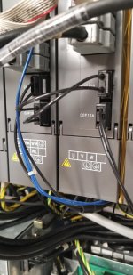
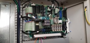
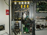
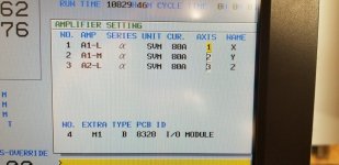
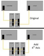
I purchased a used Kitagawa MR320. I know, big for the Robodrill but was too good a deal to pass up. I also purchased a servo amp, all interconnect cables and the 4th axis wiring harnesses (motor and encoder). I got these all installed easy enough. Double checked the wiring pinout diagramed in the manuals. Everything looked good. I then followed the "additional axis" install guide in the Robodrill manual. The exact motor in the Kitagawa wasn't a listed option as it is much newer than the Robodrill. I selected a similar sized motor and did the other required parameter mods listed in the manual then the obligatory power down. I am now getting alarm #'s 478 - A Axis illegal axis data(MNT) and 496 - A Axis illegal axis data(CNC). Manual says this is normal after modifying servo amplifier configuration and to set bit 4 of parameter 2212 to a 1 and then back to 0 and do a full power down reset. Well, I've done that, multiple times, and it just keeps coming back.

I've tried manually reviewing all the parameters set for the A-Axis but they all look reasonable. I've tried reordering the Z and A axis amps in parameters 1023, and 1910-14 and 1920-24. I've tried manually inputting the motor parameters for the actual motor in the Kitagawa (C8/2000i). I've tried selecting other stock motors in the Restoration->Add Axis Parameters menu. I'm at a loss! Always get this A-Axis illegal parameter alarm, sometimes many more alarms depending what I'm trying above.

I've shoehorned this mill into my garage for a past time so don't have the time/schedule or money to try factory service support. I've also heard nothing but nightmares with guys dealing with MMT here on the east coast. Looking for a little knowledgeable DIY advice to get this 4th axis up and running.

Relevant specs:
2001 Fanuc Robodrill a-T14iBL
2012 Kitagawa MR320 with C8/2000i motor (A06b-0226-B201) i1000 incremental encoder
Servo amp A06B-6096-H103, same 6096 series as the other 2 amps for X, Y & Z
Servo SW version 90A5/04

20201028_131713.jpg
20201028_145734 (2).jpg
20201028_145831.jpg
 
I am doing exacctly what you are doing. Putting a 4th on a Robo.
my book (30i series) says the same thing about both alarms. One for the amp and one for the CNC.

SV0496
ILLEGAL AXIS DATA(CNC)
The CNC detected that an error
occurred during transfer of axis data. When an alarm occurred because the configuration of the servo amplifier was changed,
set the axis number for the servo amplifier (set bit 4 of parameter No. 2212 of the corresponding axis to 1 and 0 again and turn off the power
of the entire system). When using a multiaxis amplifier, this operation may not clear the alarm. In this case, repeat this operation for the axes on
which the alarm persists. If an alarm occurs due to a cause other than the above,

replace the servo amplifier

H103 is too small for your other single axis amp isnt it? If not you could swap it and see if it is the amp.
That motor is too big for that amp, but I dont know if that is a problem.
But if you buy another amp, get a bigger one.
 
The C8 motor in the rotary is only a 4 amp motor. I used the Fanuc motor descriptions manual (GFZ-65262EN/01) to select the amp. That's where I got the H103 from, chart on page 5.
Yeah, it is way to small to swap out for the other single amp, Z axis. That one is a H105. I don't think it is a sizing issue though. I've selected bunch of the preset motors from the Restoration menu and always get the same 2 alarms. I've tried it with the motor connected and disconnected, no difference. I would think I could get the amp configured without even having a motor connected but don't really know. The Robo manual doesn't talk about hooking up the hardware and I haven't found any guides on adding an axis. If anyone has any tips on the order of operations for adding hardware that would be great.
As for clearing the alarms, it seems weird that you just toggle that one bit without say setting it to 1 and doing a power cycle then returning it to 0 and doing another power cycle. How long do you wait between setting it to 1 then back to 0? Do I need to set it to 1 then turn off PWE? Cycle e-stop? Just seems weird to quickly toggle one bit. It doesn't seem to do anything. I have been doing the full power down too, flip breaker off and wait a couple minutes for the fans to spool all the way down.
I hope it's not the amp. Just bought it and have no other way to test it. Said it was "fully tested" for what ever that is worth. Have to see if I still have some type of warranty. Not even sure I'm past 30 days from purchase.
Hopefully your install goes smoother. It really was pretty easy to do right up until the alarm.
Did think I'd add that this is a 16iMA control. Didn't know when I bought it how much better the B model was than the A or I would have found a different machine. Ohh well...
20201025_160534.jpg
 
I don't know enough to help you except to suggest that you try calling Fanuc directly. Their phone support is free. I don't have a Robodrill, but I have talked to those dudes many times about my machines with Fanuc controls. Since you're already so deep into this, you might just need a little info from them to get this done. 888-FANUC-US
 
My bad.I dont have any documentation for specifying motors of that era. I was just going by the #8 in the motor number as you would on current gen alpha.
If you get the alarm still in estop. You could swap it for Z (I think Z is the single axis amp) but never release the estop state so the amp doesnt actually have to drive that big motor and large load of the head.

See if the alarm follows it to Z.
 
wmpy, thanks for the number. Didn't know there was a free help line. Have to wait until I'm back out in the shop with the machine to call. Darn day job takes up too much of my time!

GENERALDISARRAY, I might try swapping out the 2 single channel amps while in E-stop like you suggest. I'm a little concerned about unplugging the Z axis encoder then having to do the reference position relearn on it once I swap back. I had tried doing the amp swap in only software when I was fiddling with it. The Z-axis amp (H105) did come up as A axis and the other way around. If I recall correctly I got the 478 & 496 alarms for both A & Z axis that time. I was thinking it was because the physical order didn't match the SW order. Like, axis number 3 was actually the 4th amp channel in the FSSB chain. Not sure though.

I did notice the JX1A->B cable I bought didn't match the stock ones. The ones that were there are dual ribbon cables were as the new one is a multi-conductor shielded deal. Pinning them out the new cable is missing some connections between pins but did have everything that was listed in the amp manual schematic. Just for kicks I swapped the new cable out for the old one going to the Z axis. Swapped out the optical too. Z axis worked fine with the new cables with the mill in plain old 3 Axis mode (9900 set to 3). Tried as 4 axis and the A amp still gets same alarms.

One last observation. The new A axis amp is a "F" series. the X/Y amp is "A" series and the Z is "E" series. Not sure if there is series incompatabilities or not. They are all A06B-6096-HXXX types.
 
I am not sure about the letters on the drive data tag, I think it is software revision level.

Is the fiberoptic supposed to land on the fourth drive first? It looks like it is in the picture.
It also looks like you dont have batteries hooked up to it.

Does the leds on the drive show a dash when its on?

Is the pulsecoder the same as the other axes?

I got mine going last night, the servo axis number 1023 was 6 . My friend sent me parameters from a 31iB with a DDR and it was 4.
Because of dual check safety. I had to setup the axis parameters through the quick screen, after the Fanuc guy enabled the option. It set it as 6.
I was getting a sv498 alarm, that wouldnt clear on power cycle. What I found was you have to completely power it down, at the main disconnect.
 
Hard to see in that pic. The fiber optic goes into the XY amp first, left one. Then bridges to the Z axis and finally the new 4th axis amp. It leaves the 4th axis amp and goes to the relay board. So when I added the A-Axis amp I unplugged the FSSB output from the z axis amp and put it on the A axis, then added a jumper between Z and A.

All the drives show the same solid dash, no Amp alarm codes being shown.

The pulsecoder is not the same on the A-Axis. The C8/2000i has an i1000 incremental encoder. Hence the reason for no battery input on the amp, the encoder doesn't need it. I did try installing the jumper wire for the battery to the A-Amp but got the same alarms.

1023 is set as 4. I don't have to use the quick screen, just set the parameters under MDI->Settings. I have been doing full main disconnect power cycles too. My alarms don't clear.

Glad to hear yours works! I think mine being an older t14iBL with 16imA there is some finicky issues I'm not aware of. I think I recall a comment somewhere saying older systems always have to have the Z axis amp last in the chain, but can't find the post now. I might monkey around with reordering the amps this weekend.
 
The FSSB line goes somewhere after the drives in your machine? I would like to see what that is!?
I think we might be getting somewhere. Do you have the connection manual? Or better would be a cabinet pic of a running Robo of the same vintage? With a fourth.
The order that they are plugged in is not arbitrary and I am pretty sure the order of cop10a or cop10b first has changed from yours to mine.
The connection manual talks about FSSB order and axis number. But it should be for your series.

I have a horizontal here with 6096 drives in it, this is how the FSSB line looks
fiber lands first on Cop10b (cop10b will be the receiving port from here on)of a dual axis drive for X and B. the X axis is on the M and B is L.
goes next to the drive for Y
then Z
then a beta drive for the APC
then another for the tool magazine
thats the end of the FSSB line on that machine

param 1023 looks like this
X=2
Y=3
Z=4
B=1
V=5
W=6
 
The FSSB does go to the I/O board after the amps. I made a diagram showing how it is wired without and with the 4th amp. There is no param in 1023 for the number of the I/O board. I recall when I had the 4th amp wired up and set to number 4 the I/O board automatically changed to 5 on the FSSB menu. I'll wire it all back up tonight and check that. If they both end up configured as 4 that might explain it.... but I wasn't getting any I/O or FSSB alarms.

The pics of my amps are without the 4th in the mix. Have it out right now so I can still use the machine.

I looked for and found a bunch of pics of Robo's with 4 and 5 axis setups. The different models look wildly different. I did find some "B" models like mine though and they look to be wired the same, with an I/O board after the last servo amp. Last pic attached is a 5 axis model, little blurry but can make out the FSSB line leaving the last amp on the right.
 

Attachments

  • 20201105_075132_resized.jpg
    20201105_075132_resized.jpg
    97.2 KB · Views: 39
  • 20201105_075141_resized.jpg
    20201105_075141_resized.jpg
    101 KB · Views: 43
  • s-l1600 (1).jpg
    s-l1600 (1).jpg
    93.9 KB · Views: 56
  • 20201105_075410_resized.jpg
    20201105_075410_resized.jpg
    93.2 KB · Views: 48
  • FSSBwiring.jpg
    FSSBwiring.jpg
    9 KB · Views: 43
can you take a pic of the exact connector on the IO board where the fiber connects?
like unplug it and look at the cable.

I cant make it out in the pic.

edit
I think thats it going onto the underside of the board?

What I was getting at, is can you come from the output side of the io board (cop10a)and go to the rotary drive?
 
Last edited:
There are 2 smaller boards behind the bigger front one. The FSSB cable goes to the small board behind on the top left. There are several ribbon cables going from the 2 boards behind to the board in the front. The part number on the front board comes up as being the main I/O board. I can't see a part number for the board behind that the FSSB actually plugs into.

There is a 2nd FSSB port on this board and it is capped off. I don't have a long enough cable to try swapping the order. I really don't think it would work that way and recall there being descriptions in the manual saying the I/O and accessory boards go after all the amps.

I hooked the 4th axis amp back up and sure enough the I/O board gets auto renumbered to 5 on the FSSB amplifier settings page. The 4th axis amp name/model number gets auto populated. I didn't enter that info anywhere so I know the amp is communicating with the controller to get that info.

All the amps just have the solid dash ( - ). the 4th axis one doesn't look any different. The system is in e-stop of course, because of the alarm they wont enable.

20201105_075141.jpg
20201106_085717.jpg
20201106_091118.jpg
20201106_085542.jpg
 
what does 40as mean?
I am at a loss I guess. I dont know what else you could do besides trying a different amp.
If you haven't already reached out to Fanuc, I would do that. You can do it via email if you register on their website. You have alot of data to feed them, sometimes the phone isnt great for that.
 
Looks like they made a SVM40-AS (H103) and a SVM40-AL (H104). The suffix just corresponds to the amp size.

I reached out to Fanuc and a couple of their techs tried to help me. I gave them all the info in this thread as well as more info on the machine and the full parameter list punch out. They verified the machine is setup with the 4th axis option and that the amp is the right size/series for this year Robo. It of course doesn't mate well with the ai motor in the rotary but shouldn't cause the alarms, especially when configured for a stock motor. The alarms are only related to the dual safety check so something isn't jiving between the amp and controller.

I also reached out to Kitagawa to try and get a recommended motor parameters list. They replied that they sold the hardware to ATS systems who in turn added the motor and wiring and resold. So i'm continuing down that path. I have the motor parameters from the Fanuc manual so not expecting much out of this, just being thorough.

All signs are pointing to a bad amp but the Fanuc guys recommended following the 4th axis motor setup exactly per the manuals (B-68934 and B-68935) via the Quick screens. Those manuals are for the B-model Robo with the 16iMA controls. I only have the manuals for the C-Model with 16iMB control so the procedure may be different. All I had to do was select a motor from the list in the quick screen and everything got auto populated. I don't see any other places in the Quick screen to do more setup and there is no other steps in the C-model manual. Fanuc wants to set me up with an account then quote me the manuals and an amp "Wash and test". Just trying to figure out how to setup a corporate account without being a business.

GENERALDISARRAY, could you tell me what alarms, if any, you get if you start your machine up with the rotary unplugged but still in e-stop? Grasping at straws here, want to rule out any potential wiring issues or see if you can induce the same alarms via hardware.

Little worried about the cost of Fanuc direct manuals and amp service. Does anyone have any 3rd party recommendations? Preferably someplace I can just pay them without setting up an account and credit line.

I'm going to continue to update this thread with what I figure out. Might help someone out in the future.
 
You can try eBay for the manuals. It might take a while to find them, though. If you want to post the part numbers for them, I can call Fanuc and get you prices. At least then you'd know how much they'd be.

For testing the drive, I recommend Tri-Star CNC and Tennessee Industrial Electronics. I mostly use Tri-Star because they're close to me and the prices have generally been better. I think a wash and test is $300-$400. And I think they waive that if a repair is needed. They also have their repair prices listed on their website for most Fanuc part #s.
 
I use KFAS down in Katy Texas. a wash and test there is also $300. I have been happy with their service.

I think you can setup a Fanuc Credit card account online, and I would guess the manuals are $35 each. Seems to be a set price from them. They can take a while though.

Some things from Fanuc are reasonably priced, others are insane. There are probably reasons I guess.
 
The manuals they recommended were B-68934 & B-68935. These are the operations and maintenance manuals for the B model Robodrill.
I can get another used but "Guaranteed" H103 amp for ~$500. Might just try that. I've still got a gut feeling that it's not the amp but rather some obscure parameter in the control. I'd like to get a parameter file from a similar machine with 4th axis to compare to. Likely just some parameter related to HRV being out of bounds or something.
For now I've back burnered the 4th axis so I can just play with the machine. Spent weeks with my new toy without making chips. Need some easy wins then I'll get back on the saddle.
 
For the manuals, you need to contact Methods, I just talked to Fanuc, and that's what they told me. You can just email Methods. I recently requested pricing on a manual for a Nakamura from them, and they ended up sending me a PDF of the manual at no charge. I had no previous relationship with them, so it was pretty cool that they did that. Maybe you could get lucky and get the manuals for free, too?
 
I did. For anyone else with this issue. You need to set bit 5 of parameter 1902 to 1. I think this enables the dual safety check for the 4th axis/3rd amp. I couldn't find a description of the bit in any of the manuals. This definitely fixed it though, 4th axis is working great now.


Back
Top