What's new
What's new

Spring force in a thicknesser.

RODELU

Aluminum
Joined
Dec 31, 2010
Location
Uruguay
How do you adjust spring tensión of feed and pressure rollers in a thicknesser? I cannot measure that tension, but need a ballpark way to set it.
I'm rebuilding an old 40cm (16in.) italian machine.
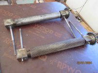
There are two idle rollers in the table underneath the feed and pressure rollers.
I found "Getting peak planer performance" in FWW, very useful but it mentions nothing about spring force, it shows what feed and pressure roller height should be with respect to the table but that is non-adjustable in my machine or in any other thicknesser I've seen.
 
Pretty straightforward, if there is not enough pressure the workpiece will not feed through the machine. Increase the pressure until you get consistent feed that is acceptable. I am guessing it may be difficult to put too much pressure on the feed rolls.
 
Pretty straightforward, if there is not enough pressure the workpiece will not feed through the machine. Increase the pressure until you get consistent feed that is acceptable. I am guessing it may be difficult to put too much pressure on the feed rolls.
Thanks for your reply. I"ll try to set the rollers according to your suggestion.
 
You can have too much pressure on the chipbreaker which causes feed problems.

Good luck
Thanks again for your reply. There's no chipbreaker I can see in my machine, but there is one in the FWW article I mentioned before; should there be one present?
 
Ideally there should be one however it is not strictly required. One of the jobs a chipbreaker does is direct the chips around the cutterhead into the dust chute.
There must be something there to direct the chips?
Can you post some pics?
 
I’m happy to post pictures of the thicknesser I’m trying to rebuild. Unfortunately the machine is stilll disassembled. It was made in Milano, Italy maybe 70 years ago by Edoardo Origgia. Everything is cast iron or 1214 steel which makes it VERY heavy. It was originally a combination machine, all that is left now is the thicknesser.
The cubes in the rollers with the springs and long threaded bars fit into the four square-shaped cavities next to the head and, once assembled, the springs abutt the lugs in picture # 1 and pull the rollers down by a still undecided amount, adjusted by the two nuts attached.
The original chute for the shavings is lost, I made one out of 1/8 in. aluminium sheet; the machine is still in pieces so I still don't know if the chute I made works or not. Perhaps I should add a piece that goes down almost to the surface of the wood being worked so the shavings will be directed out of the way.
The supports for the rollers and head are made out of cast iron; one of the square-shaped cavities for the cubes attached to the rollers has a very neat and original brass welding that shows the same traces of machining as the other cavities. We all make mistakes….
Any and all suggestions will be welcomed!
 

Attachments

  • Thicknesser 1.jpg
    Thicknesser 1.jpg
    553.2 KB · Views: 10
  • THICKNESSER 2.jpg
    THICKNESSER 2.jpg
    682.7 KB · Views: 10
  • Thicknesser 3.jpg
    Thicknesser 3.jpg
    658.7 KB · Views: 10
  • Thicknesser 4.jpg
    Thicknesser 4.jpg
    532.2 KB · Views: 10
  • Thicknesser 5.jpg
    Thicknesser 5.jpg
    486.3 KB · Views: 10
You won’t have any trouble setting the spring pressure.
The infeed roll looks a little bit well worn though which will not help with the feed. Make a little carbide scraper and use it to clean out each scallop and remove the imperfections while restoring some sharpness to the leading edge.
Make sure that the infeed roll and the outfeed roll are exactly the same diameter. If they are not then feed problems are inevitable. Don’t ask me how I know that….
 
I would set the rolls at about 1/8” below the cutterhead and see how that performs. One metric is if the infeed roll embosses the workpiece so much that a fine cut setting does not remove the marks. This can happen on narrower workpieces.
My guess is that this setup will produce some snipe and you will just have to live with it. Flush to table setting on the bottom rolls will help but may not eliminate the snipe.
If you have a truckload of material to plane for fencing then set your bottom rolls higher for easier feeding.
For fine finish work set them down flush and use lots of hard wax. Some machines had a one lever adjuster for the bottom rolls.
 
You are right about the serrations in the feed roll, I have to improve those; sort of like sharpening a hand saw, you start by making all the teeth the same height.
I have a Bridgeport, I'll try to make new teeth in it and then turn the outfeed roll to whatever diameter I end up with.
 
The rolls in this machine cannot be adjusted in height (other than by shimming) but you can adjust how much the blades protrude with respect to the cutterhead, so adjusting the blades is (probably) the way to do it.
However, that 1/8" will disappear once the machine is operating, you'll remove perhaps something less than 1/8", your feed roll will then be above the blades, and your pressure roll willl be level with the blades; am I missing something? Is that 1/4" or so the ballpark number I'm looking for?

Good suggestion about the depth of the marks produced by the feed roll, I'll try that once the machine is working again.

I didn't know that trick with the table rolls for fine finish, the table rolls each has a cup greaser and their height can be adjusted by a screw and lug nut; good design!
 
You won’t have any trouble setting the spring pressure.
The infeed roll looks a little bit well worn though which will not help with the feed. Make a little carbide scraper and use it to clean out each scallop and remove the imperfections while restoring some sharpness to the leading edge.
Make sure that the infeed roll and the outfeed roll are exactly the same diameter. If they are not then feed problems are inevitable. Don’t ask me how I know that….
This might be a very silly question: why should the rollers be the same diameter? again, am I missing something?
 
The rollers need to be the same diameter as they are driven together. If one is larger or smaller then they will rotate with a different travel distance per revolution. A small amount adds up when you multiply by three.
The difference causes one roller to fight against the other as the stock is feeding, if the material slips on the smooth outfeed roller you may never notice.
In my case the slack in the drive chain loaded up and then released each full revolution causing a witness mark in the material which drove me nuts for a few years until I figured it out and made a new infeed roll.
 
Yes, of course the feed rolls will bottom out when installed and the only motion will be upward as the stock feeds into the machine. So check the height of the blades when normally set into the cutterhead and check the feed roll height to compare.
It should be designed so that the blades protrude just out of the cutterhead so the back bevel is close to flush with the OD or maybe a 1/16th beyond.
When doing these height checks you can check for parallel on the feed rolls and cutter to the table.
Even a very small difference here will show up so getting it perfect pays off.
 
In regards to restoring the infeed roll serrations I would just scrape them clean as I mentioned rather than cutting all new grooves. It will feed the stock as it is now so save yourself some time and get it running.
If you ended up changing the diameter then it will affect the knife projection.
I just noticed your indicator holder for checking the roll and cutter height. You could also just install one knife while it is on the bench and use a straightedge to check the feed roll height to knife height.
 
Good thinking!! saves me a lot of aggravation.
I made the dial indicator holders according to what the article in Fine Wood Working suggested.
As I said before, it´s a very old machine, heavily used, and don´t know wether I should make the head parallel to the table or make the knives parallel to the table.
Another detail of good design, the knives can be raised when mounted in the head by 6mm Allen-head screws, first time I see that method, I had seen flat springs only for that purpose; anyway, mounting the knives in the head is still in the future,
 
You should definitely make the cutterhead parallel with the table. Then the knives are automatically set parallel with the cutterhead.
Usually the table can be adjusted into perfection however without seeing what you have that is only speculation.
My machine is also Italian and from the early 1980’s. It was most definitely heavily used and abused. I can’t quite figure out how they managed to gouge the table so badly as it appears part of the segmented infeed roll dropped down and rubbed gouges into the table. It seems like anyone with half a brain would notice that right away…..
So now it doesn’t have a segmented infeed roll as the replacement was rather expensive. (it didn’t have one when I bought it) After quite a bit of work it now cuts very well and is a pleasure to use. The analog digital meter is also surprisingly accurate to one tenth of a millimeter.


Back
Top