What's new
What's new

Standards on Internal Diameter Knurling?

Blough

Aluminum
Joined
Aug 19, 2017
Location
Akron-Canton
This part we make is intended to be press-fit over a plastic tube, the ID is knurled.
We have been having issues with tolerancing, and I have been assigned to review the part and make sure it was designed correctly.
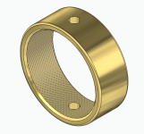
1659363438346.png

First thing is to familiarize myself with the knurling process.
Since it is a process of displacing material instead of removing it, the tolerances of the blank are a lot more important.

I see that there are relevant standards that guide the design of blanks to be knurled such as ANSI/ASME B94.6-1984 (2014)

But I've noticed the standard only refers to outside knurls. Are the tolerance classes interchangeable with internal knurls as well?

(Also I want to make a note that I do not believe there is any advantage to knurling on this part, it gets fitted on a turned piece of G10 laminate and pinned with the thru hole. But "Thats how we have always done it")
 
Hi Blough:
One of the things you must remember about internal bump knurling vs external bump knurling is that the displaced metal does different things to your part, depending on which kind of knurling you're doing.

When you external knurl, the part diameter increases a bit and the end(s) of the knurled area get displaced endwise as the metal flows along the path of least resistance.

When you internal knurl on a thinwall tube as you're showing, the part diameter increases a lot because the skinny wall can't resist the bump knurl forces so the ring grows in diameter.

If you are familiar with how a sheet metal stretcher works, (like Autobody guys use) you will see one of those sources of diameter growth.
If you look at how metal spinning works, you will see the other.
If you support the OD of the part with a roller bearing, it will expand like happens with a stretcher.
If you don't it will be more like metal spinning.

So if you start with a thick wall tube and turn it down after knurling, or if you chuck the part in a pot collet before knurling it will grow completely differently than when you turn a cup on the end of a bar, or bore out a skinny tube and then stuff the knurler in there with the OD unsupported.

So diameter control becomes a tricky thing, and depends on how you do the job.

A more consistent way forward is to skive, cut knurl or cross thread the ID(left hand thread and right hand thread in the same bore); this reduces the forces and their variability a lot and will enable you to make much more consistent parts but it takes longer.

Going back to your question, since the effects of the forces are so different from ID vs OD bump knurling, you cannot rely on the standards for OD knurled blanks.
You have to settle on your material, your fixturing method and your processing method first, and then then empirically determine your proper blank size (trial and error).
Since the forces are so variable with bump (displacement) knurling and depend on everything from material hardness to lubricant cleanliness, you can chase your tail forever trying to achieve dimension consistency.

If you need to hit tighter tolerances, I'd be investigating cut knurling options like cross threading.
That you can control really easily, and it's much more forgiving of variables like material hardness.
Since you are convinced these knurls are mostly cosmetic anyway, you probably need not care that they were processed by chip making rather than by metal displacement.
Be aware though, that the local material properties will be different if they are cut compared to if they are displacement knurled.

Cheers

Marcus
www.implant-mechanix.com
www.vancouverwireedm.com
 
Last edited:


Back
Top