What's new
What's new

.008" Slitting Saw-Student needs help!

aggiecow

Plastic
Joined
Aug 11, 2023
Hi everyone!

I am a student at UC Davis, by no means experienced in machining (or anything really). I am attempting to make a series of slots in 6061, .030" deep, .008" wide and 2" long. The distance between each parallel slot is .010". I have had some limited success using a 1” x .008” 98 tooth HSS slitting saw on a Sierra American precision arbor, but my issue is that progress is incredibly slow.

The best combination I have stumbled on is conventionally cutting 3 passes @ .010" DOC each, 800 RPM and feed of 3 IPM. I should mention that I am currently using a Bridgeport mill, but eventually I will have access to a TM-0P. I have tried increasing RPM as well as feed, but whenever I do the "ridge" between the slots tends to curl towards the previous slot. For the part I'm making it's imperative that these ridges are straight. Due to my inexperience, I am not sure how much the information online which pertains to SFM, IPM and IPT applies to my situation. I am hoping someone with more experience can help a novice out!

As far as coolant goes, I am using a mister as well as additional compressed air to try to push chips out of the cut.

Does anyone have any tips on making this feature faster? I am mainly looking for advice on DOC and feeds/speeds, but any advice at all is very welcome.

Nick
 
Are you making through slots or just grooves? Big difference.

Lets say that it's already complete, by whatever method. What do you have remaining? 0.010" thick aluminum webs, 0.030" thick, 2" long? That's not much more than flat aluminum wire. If you're cutting this all the way through, it's going to be fragile as heck when it's done.

I would say that using the Haas, you might be able to take very precise, very light but deliberate cuts. The meat servo operating the Bridgeport doesn't have the finesse the CNC will. I'd cut them most of the way through, leaving a web to stabilize each, then cut the final depth at the end. It's still a tall order and probably won't work.

The way it could be made would be wire EDM. Very expensive but, zero pressure on the material. Still a tall order because wroght materials have internal stresses that will be released as it's cut. As the EDM slices through the material, those stresses may bow each fin, which may not be straight enough to cut the second side. This too can be mitigated but, I suspect you don't have that kind of budget.

Can this be redesigned? Why do you need the features to be this way?
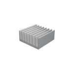
You are correct in that they are grooves, not slots. The substrate that they are being cut into is .25". The design is similar to a typical parallel-plate fin heat sink, except on a much smaller scale.
MFG_TGH-0522-01.jpg

Unfortunately it can't be redesigned as it is part of an experiment to validate some heat transfer research. The grooves will serve as microchannels for fluid flow and the aspect ratio of the "ridges" is important to the design's effectiveness.

I think I mentioned in my post that we have some samples that were made a few years ago, but unfortunately the person who made them isn't available to give details. All I know is that he used a slitting saw.

Thank you for taking the time to respond!!
 
Am I right that you're leaving .002" ridges. 030" high? What about cutting every other slot and then come back and do the rest. That way the cutting pressure on the remaining material is a lot more even. Otherwise, as @Donkey Hotey says, EDM would be a good option. Speaking as a thirty year physics lab rat, this does seam like a weird part that needs to be thought about. What's with the 50 micron ridges anyway?
 
Am I right that you're leaving .002" ridges. 030" high? What about cutting every other slot and then come back and do the rest. That way the cutting pressure on the remaining material is a lot more even. Otherwise, as @Donkey Hotey says, EDM would be a good option. Speaking as a thirty year physics lab rat, this does seam like a weird part that needs to be thought about. What's with the 50 micron ridges anyway?
I would be leaving .010” wide ridges, .030” high.

EDM could work, but for now I am just trying to recreate the parts we have now (following the same manufacturing method).

Thanks for the reply!
 
Unfortunately it can't be redesigned as it is part of an experiment to validate some heat transfer research. The grooves will serve as microchannels for fluid flow and the aspect ratio of the "ridges" is important to the design's effectiveness.

Awesome. Your work? Engineering student?

Yeah, given the new information, you could continue with the slitting saw to create the features. Take advantage of the fact that the Haas is patient and tenacious. The cutting will need to be slow. What software are you using for doing the cutter paths?

In Mastercam, I'd use 2D profile. I'd pick the 'root' of each groove as single entities for the geometry. If you set your depth to relative, each slice will use the Z depth of the element. Then I'd use multi-passes, take very light cuts (0.003-0.005" deep?) and as many as it takes to get to final depth. Lead in and lead out as necessary to nurse the part and clear everything.

What that will do is slice each one just a little, moving down to the next fin, the next, the next. At the end it will start again at the top and take another small slice at the set. The fins will be stablilized to the bottom of the groove because the material is still there. The saw may rub so keep it flooded with coolant if you can.

So you're studying the heat transfer of aluminum through changing the aspect ratios of the fins? Some new area of study? I thought the transfer of heat was fairly well known in numnum.
 
You did not say what coolant you are using. Is it one that is formulated for aluminum? This could make a big difference.

If yours is not intended for aluminum, I would try WD-40 and see how that works. And be generous with it: a stream, not a mist. Or use a squirt bottle with frequent squirts.

Others here may have better suggestions. That's just off the top of my head.
 
Awesome. Your work? Engineering student?

Yeah, given the new information, you could continue with the slitting saw to create the features. Take advantage of the fact that the Haas is patient and tenacious. The cutting will need to be slow. What software are you using for doing the cutter paths?

In Mastercam, I'd use 2D profile. I'd pick the 'root' of each groove as single entities for the geometry. If you set your depth to relative, each slice will use the Z depth of the element. Then I'd use multi-passes, take very light cuts (0.003-0.005" deep?) and as many as it takes to get to final depth. Lead in and lead out as necessary to nurse the part and clear everything.

What that will do is slice each one just a little, moving down to the next fin, the next, the next. At the end it will start again at the top and take another small slice at the set. The fins will be stablilized to the bottom of the groove because the material is still there. The saw may rub so keep it flooded with coolant if you can.

So you're studying the heat transfer of aluminum through changing the aspect ratios of the fins? Some new area of study? I thought the transfer of heat was fairly well known in numnum.
It is not my work, I am but an intern. I am a mechanical engineering student!

I am currently using fusion 360, but I think I understand your explanation. Thank you for taking the time to detail so clearly. I'm not sure how to optimize the different parameters for cutting. Is it best to first identify a SFM value and then change feed rate or cut depth until I find the the optimal balance between making the part quickly and finish quality? What do you think of the feeds/speeds I have listed above? My main concern is that the IPT (.0004") seems ridiculously low compared to the information I've found. Is that to be expected for such small tooling?

The group is working on cooling solutions for a variety of applications. Apparently with the advancements of manufacturing processes come new and interesting geometries to examine, some resulting in an increased effectiveness of ~50% over current methods.
 
You did not say what coolant you are using. Is it one that is formulated for aluminum? This could make a big difference.

If yours is not intended for aluminum, I would try WD-40 and see how that works. And be generous with it: a stream, not a mist. Or use a squirt bottle with frequent squirts.

Others here may have better suggestions. That's just off the top of my head.
Thank you Paul.

I believe the coolant is formulated for aluminum, but I will have to double check. Aluminum is the main material that we use in the shop.

I will have to give the WD-40 a try!
 
I'm not a super fan of doing delicate work with a slitting saw so I'm gonna' toss another suggestion in there:


It's a 3-flute, carbide Harvey endmill with 0.040 max depth of cut. I'd prefer this method over the slitting saw. When you don't know feeds and depths, it helps to simply scale something you know that's conservative. Being so long and slender, you want to err on the side of very conservative cuts or it will snap.

You can fully engage a 1/2" endmill at 0.003" per tooth feedrate in aluminum, one diameter deep, without much issue. Scaling that down: the 1/2" endmill is 63.5 times the diameter of your 0.008. Divide the 0.003 by 63.5 and you get 0.000047" feed per tooth. Multiply that by 3 teeth to get a feedrate of 0.00014" per revolution.

The Haas website says the TM0P has a 6K spindle so 6K x the feed per revolution = 0.85 IPM feed rate and 6K rpm. That's probably about right. Take less than one diameter deep passes so 0.004-0.006" deep each. Keep it flooded or the mill will pack up with aluminum and break. You'll need a magnifier to even check it. Program it and let it run. It'll be slow but, I've done some stupid small stuff this way and it can be done on the Haas.
 
What do you think of the feeds/speeds I have listed above? My main concern is that the IPT (.0004") seems ridiculously low compared to the information I've found.
The problem here is the geometry of using a relatively giant 'saw' to cut such a delicate feature. If you draw what you're doing in Fusion, you'll see that most of the teeth are just rubbing the aluminum. The only part cutting is the very front of the cut, where the teeth are climbing into the cut and taking a bite. Problem is: after it takes that first bite, the aluminum can't get out of the teeth until it comes out the other side. The teeth are so close together that there's nowhere for the chips to go. You're fighting the chip packing more than you're really cutting.

Same with a bandsaw. A blade suitable for aluminum has very coarse teeth and looks more suited for cutting wood. This is because the aluminum can be cut aggressively but, there must be somewhere for the chips to go until they clear the cut and can be ejected.

Get as much lab time as you can as an engineering student. Soooo many graduate with no knowledge of how things are actually made and what can and can't be accomplished.
 
Oh, one more thought. You said 6061 which I assume is aluminum. But there is 6061 which can be quite gummy and 6061-T6 which is harder and machines quite differently.

Which are you using? And if it is the plain 6061, can you switch to the 6061-T6 instead?
 
The problem here is the geometry of using a relatively giant 'saw' to cut such a delicate feature. If you draw what you're doing in Fusion, you'll see that most of the teeth are just rubbing the aluminum. The only part cutting is the very front of the cut, where the teeth are climbing into the cut and taking a bite. Problem is: after it takes that first bite, the aluminum can't get out of the teeth until it comes out the other side. The teeth are so close together that there's nowhere for the chips to go. You're fighting the chip packing more than you're really cutting.

Same with a bandsaw. A blade suitable for aluminum has very coarse teeth and looks more suited for cutting wood. This is because the aluminum can be cut aggressively but, there must be somewhere for the chips to go until they clear the cut and can be ejected.

Get as much lab time as you can as an engineering student. Soooo many graduate with no knowledge of how things are actually made and what can and can't be accomplished.
Thank you for the explanation. Would it make sense in this case to remove every other tooth (or more) from the blade?

I appreciate all of your help and advice!
 
I'm not a super fan of doing delicate work with a slitting saw so I'm gonna' toss another suggestion in there:


It's a 3-flute, carbide Harvey endmill with 0.040 max depth of cut. I'd prefer this method over the slitting saw. When you don't know feeds and depths, it helps to simply scale something you know that's conservative. Being so long and slender, you want to err on the side of very conservative cuts or it will snap.

You can fully engage a 1/2" endmill at 0.003" per tooth feedrate in aluminum, one diameter deep, without much issue. Scaling that down: the 1/2" endmill is 63.5 times the diameter of your 0.008. Divide the 0.003 by 63.5 and you get 0.000047" feed per tooth. Multiply that by 3 teeth to get a feedrate of 0.00014" per revolution.

The Haas website says the TM0P has a 6K spindle so 6K x the feed per revolution = 0.85 IPM feed rate and 6K rpm. That's probably about right. Take less than one diameter deep passes so 0.004-0.006" deep each. Keep it flooded or the mill will pack up with aluminum and break. You'll need a magnifier to even check it. Program it and let it run. It'll be slow but, I've done some stupid small stuff this way and it can be done on the Haas.
I will take a look at this option as well, thank you for the suggestion.
 
Oh, one more thought. You said 6061 which I assume is aluminum. But there is 6061 which can be quite gummy and 6061-T6 which is harder and machines quite differently.

Which are you using? And if it is the plain 6061, can you switch to the 6061-T6 instead?
I am using T6511. I believe that should have roughly the same machinability of regular T6? Please correct me if I'm wrong.
 
Thank you for the explanation. Would it make sense in this case to remove every other tooth (or more) from the blade?

I appreciate all of your help and advice!
I wouldn't try to remove teeth from the existing blade. MSC lists teeth for a 1" slitting saw in 12, 16, 24 teeth, etc. You don't need to go all the way down to 12 but, something with more clearance for chips would make it easier going. You want teeth in the cut since they stabilize the blade. You just don't want a bunch of teeth in the cut, all clogged with aluminum. Maybe 24? Hard to pin down an exact answer. They only have one option in stock so you'll need to shop somewhere else. I just used them for comparison.

For comparison: if we were talking about a 1" diameter endmill, doing normal cutting in aluminum, it would be no more than 4 flutes, to allow for ample chip clearance. Maybe 5 in an unusual case. You're doing the same thing, only thinner. 80 teeth is wayyyy out there.
 
I second that, high teeth number = thin material where you are trying to spread the load and there is not much material
 
I wouldn't try to remove teeth from the existing blade. MSC lists teeth for a 1" slitting saw in 12, 16, 24 teeth, etc. You don't need to go all the way down to 12 but, something with more clearance for chips would make it easier going. You want teeth in the cut since they stabilize the blade. You just don't want a bunch of teeth in the cut, all clogged with aluminum. Maybe 24? Hard to pin down an exact answer. They only have one option in stock so you'll need to shop somewhere else. I just used them for comparison.

For comparison: if we were talking about a 1" diameter endmill, doing normal cutting in aluminum, it would be no more than 4 flutes, to allow for ample chip clearance. Maybe 5 in an unusual case. You're doing the same thing, only thinner. 80 teeth is wayyyy out there.
This makes sense. Would the lower number of teeth affect the finish at all?
 
This makes sense. Would the lower number of teeth affect the finish at all?
That's the dance with the devil. All those teeth dragging inside the cut are also stabilizing the blade. You don't want so few that you don't have 3-5 teeth in the slot at all times. If that happens, the teeth may be going into the cut, unguided. They may chip and scratch the adjacent walls.

1" diameter saw? So 3.1416 circumference? 98 teeth? That works out to 0.032" between teeth. There is no place for the chips. You could try to use what you have but, shallow cuts so you don't load the gullets with material. Lots of shallow passes.
 
A slitting tool is fundamentally a cutting tool not a grooving tool. Its comfort zone is going through relatively thin material as close to on diameter as can be arranged so each tooth makes a cut and carries the cut material in its gullet pretty much straight up through what you are cutting.

You are working at a very shallow depth at the very bottom of the cutter which is a very different thing. As has been said more scraping than cutting. Almost ploughing. It's getting close to the sort of thing the ruling engines that made diffraction gratings back in the day did. Possibly some inspiration on techniques there.

Gotta wonder whether a wide, stationary, multi groove cutter pushed across it in 10 thou cut steps might work. Think of something like a die head chaser. Or spinning a special straight line knurling wheel, with parallel sides to the forming ridges rather than the usual angled ones, interrupted at intervals so it cuts. Heck its only alloy maybe leaning hard on a knurling type tool would do the deed, part cut, part extrusion.

Do the sides have to be vertical? If it's for cooling purposes the slots seem way too close and way too narrow for proper flow. But its a long time since I had owt to do with such stuff and the art has evolved.

A 12 tooth, small diameter, saw sounds well with trying. I have a 10 tooth one, albeit thicker, that works well on appropriate jobs where only the bottom can engage.

Clive


Back
Top